Web Configuration Guide
This guide outlines the router’s menu structure, providing a straightforward approach to configuring your router settings.
System Settings
Basic Setup
Here, you can personalize the language of the router’s configuration interface and set a recognizable hostname for the device.
Basic Settings Overview:
Parameter |
Description |
Default |
|---|---|---|
Language |
Select the interface language |
English |
Host Name |
Assign a name to the router for easy identification |
Router |
System Time
Accurate system time is crucial for reliable logs and communication between devices. Manually set the router’s time or sync it with NTP servers to maintain correct timing across your network.
Time Configuration Details:
Parameter |
Description |
Default |
|---|---|---|
Router Time |
Shows the router’s current time |
- |
PC Time |
Displays the current time of the connected computer |
- |
Timezone |
Choose the router’s timezone |
Custom |
Custom TZ String |
Specify the Time Zone string for the router |
STD-1 |
Auto-update Time |
Set how often the router updates its time |
On startup |
NTP Time Servers |
Specify NTP servers for time synchronization |
1.pool.ntp.org |
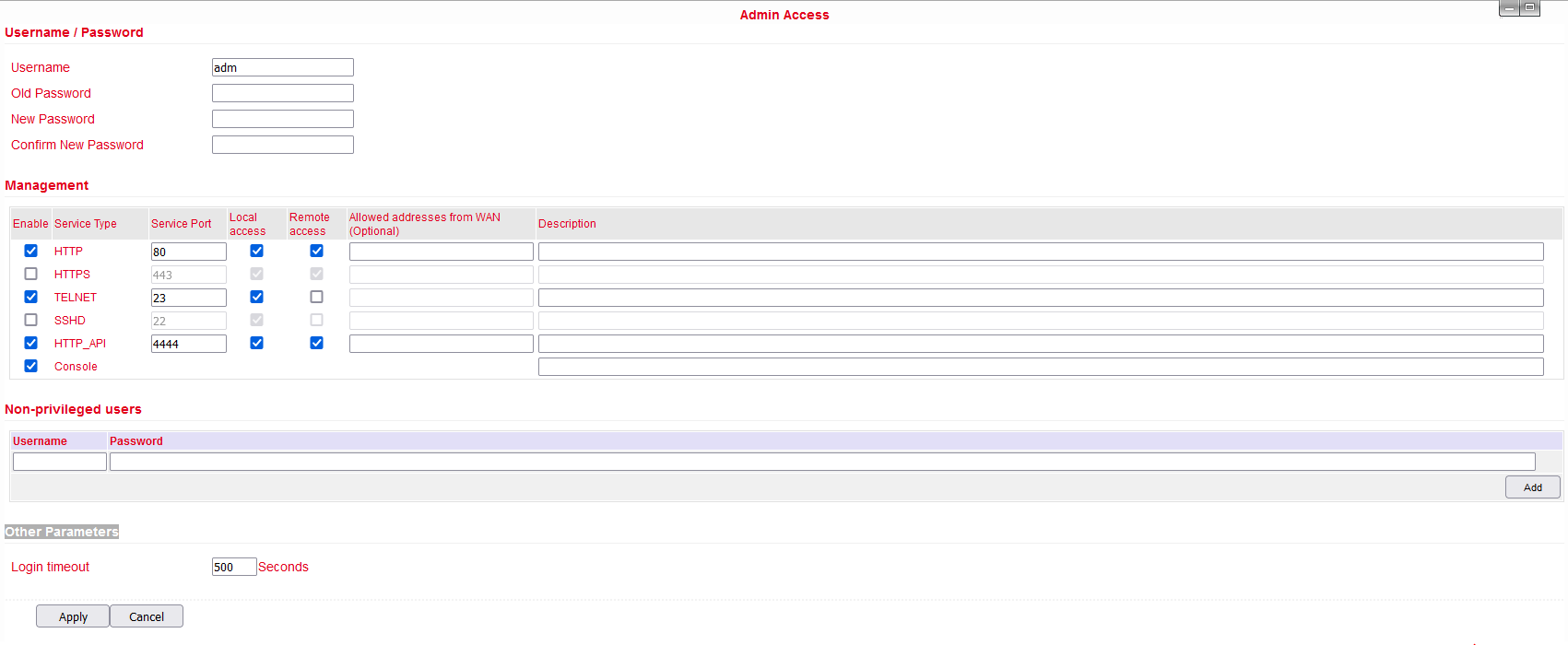
Admin Access
Configure security settings, including username and password modifications, and set access restrictions for both local and remote connections.
Access Control Settings
Username / Password: Manage the default user “adm” credentials.
Management: Options to grant access, with potential restrictions for local and remote access, including address whitelisting.
Remote Access: Enable different protocols such as HTTP, HTTPS for browser access, Telnet, and SSHD for console applications, and a Web API for external applications to interact with the router.
Local Access: Connect locally using a serial connection via RS232 (not available with IO variants).
Non-privileged Users: Create read-only accounts with specified access levels.
Other Parameters: Set a login timeout to automatically log users out after a period of inactivity.
System Log Configuration
Easily configure your system logs to be uploaded to a remote server through the “System Log Settings.” This capability is essential for integrating with remote log monitoring software like Kiwi Syslog Daemon. Once installed, configure Kiwi Syslog Daemon by navigating through “File >> Setup >> Input >> UDP.”
Access the system log settings by selecting “System >> System Log” from the navigation tree. Here, you can configure the IP address and port of the remote log server to capture and store your router’s logs.
System Log Settings:
Parameter |
Description |
Default |
|---|---|---|
Log to Remote System |
Toggle to enable logging to a remote server |
Disabled |
Log server address and port (UDP) |
Specify the remote server’s address and UDP port |
N/A: 514 |
Log to Console |
Direct log outputs to a connected serial port |
Disabled |
Config Management
Manage your router’s configuration efficiently by backing up parameters, importing backups, or resetting to factory defaults through the “Config Management” page.
Navigate: Select “System >> Config Management” from the navigation menu.
Config Management Options:
Parameter |
Description |
Default |
|---|---|---|
Browse |
Select a configuration file for import |
N/A |
Import |
Apply a configuration file to the router |
N/A |
Backup |
Save the current configuration to a host system |
N/A |
Restore default configuration |
Reset the router to factory settings (takes effect after reboot) |
N/A |
Disable the hardware reset button |
Prevent use of the router’s physical reset button |
Disabled |
Modem drive program |
Configure the modem’s drive program |
N/A |
Network Provider (ISP) |
Set parameters like APN, username, and password for ISPs |
N/A |

Ensure the validity and order of configurations when importing. The router will execute the imported configurations serially after a system reboot. Misordered configurations might prevent the router from reaching the desired operational state.

To ensure that changes in configurations or restorations to default settings are effective without disrupting current system operations, it’s necessary to restart the device after making these adjustments.
System Scheduling
Enable scheduled reboots to ensure optimal performance and updates. Access this function through “System >> Schedule.”
Scheduler Settings:
Parameter |
Description |
Default |
|---|---|---|
Enable |
Toggle scheduler to enable or disable system reboots |
Disabled |
Time |
Set the specific time for the reboot |
0:00 |
Days |
Define reboot frequency (e.g., daily) |
Everyday |
Show advanced options |
Access detailed scheduling rules for custom reboot timing |
Disabled |
Reboot after dialed |
Automatically reboot the router after a successful dial-up |
N/A |
Upgrade
The firmware upgrade process involves two main steps. Initially, the firmware is saved in a backup file zone. During a system restart, this firmware is then transferred to the main firmware zone. It is critical not to interact with the web interface during this upgrade as it might disrupt the process.
Procedure:
Navigate to “System >> Upgrade” to access the Upgrade page.
Click
Browseto select the appropriate firmware upgrade file.Click
Upgrade, thenOKto initiate the upgrade process.Once the firmware upgrade is successful, click
Rebootto restart the device and complete the installation.
Reboot
Ensure you save any new configurations before rebooting. Unsaved changes will be lost once the system restarts.
To proceed with the system reboot, go to “System >> Reboot” and click OK.
Logout
To securely log out of the system, navigate to “System >> Logout” and click OK to end your session.
Network Configuration
Cellular Connectivity
Insert a SIM card to enable wireless network connectivity through the router. Navigate to “Network >> Dial Interface” to configure cellular settings.
Cellular Connection Details
Parameter |
Description |
Default |
|---|---|---|
Enable |
Activates cellular dialup for internet access. |
Enabled |
Time Schedule |
Specifies when the router should automatically attempt to connect. |
All Times |
Force Reboot |
Router will reboot if unable to connect within a designated time and retry limit. |
Enabled |
Shared Connection (NAT) |
Allows devices connected to the router to access the internet. |
Enabled |
Default Route |
Configures the router to manage default network traffic routing. |
Enabled |
SIM1 Network Provider |
Select the network service provider for SIM1. |
Profile 1 |
Network Type |
Choose the type of network to connect (Auto mode will cycle through 4G, 3G, 2G). |
Auto |
Connection Mode |
Defines how the router connects to the internet (options include Always Online, Connect on Demand, and Manual). |
Always Online |
Redial Interval |
Time between redial attempts after a failed connection attempt. |
30 seconds |
Dual SIM Support |
Enable or disable the use of a second SIM card. |
Disabled |
SIM2 Network Provider |
Configure the network provider for the second SIM card. |
Profile 1 |
SIM2 ICCID |
ICCID number for SIM2. |
N/A |
SIM2 PIN Code |
PIN code for SIM2. |
N/A |
Primary SIM Selection |
Select which SIM card to use primarily for connections. |
SIM1 |
Max Dial Attempts |
Maximum number of dial attempts before switching SIM cards or taking other recovery actions. |
5 |
Signal Quality Threshold |
Signal strength threshold for switching SIM cards if signal is inadequate. |
0 (Disabled) |
Minimum Connection Time |
Minimum duration for each connection attempt. |
0 (Disabled) |
Initial Commands |
Custom AT commands executed at the start of each dialing session. |
AT |
MTU |
Maximum transmission unit size for the network connection. |
1500 bytes |
Use Peer DNS |
Whether to use DNS settings provided by the network peer. |
Enabled |
Link Detection Interval |
Frequency of link status checks. |
55 seconds |
Debugging |
Enable detailed logging for troubleshooting. |
Disabled |
Modem Debugging* |
Direct modem debug output to the console. |
Disabled |
ICMP Detection Mode |
Method for checking network link status using ICMP packets. |
Ignore Traffic |
ICMP Server |
Server address for ICMP network link checks. |
N/A |
ICMP Check Interval |
Frequency of ICMP checks for network link status. |
30 seconds |
ICMP Timeout |
Timeout for considering the network link as down based on ICMP response. |
20 seconds |
ICMP Retry Limit |
Maximum retry attempts for ICMP checks before considering the link down. |
5 |
*Not all models support this feature.
Scheduled Cellular Management
Configure the router to connect or disconnect based on a defined schedule:
Parameter |
Description |
Default |
|---|---|---|
Schedule Name |
Identifier for the connection schedule. |
schedule1 |
Active Days |
Days of the week when the schedule is active. |
|
Time Range 1 |
First active time window. |
9:00-12:00 |
Time Range 2 |
Second active time window. |
14:00-18:00 |
Time Range 3 |
Third active time window. |
0:00-0:00 |
Description |
Notes about the schedule’s purpose or settings. |
N/A |
WAN Configuration
Navigate to Network > WAN to configure the WAN port settings, accommodating different connection types including Static IP, DHCP (dynamic address), and ADSL (PPPoE) dialing.
Overview
DHCP: Operates in a Client/Server mode where the client requests configuration from the server, which assigns dynamic IP addresses and related network settings.
PPPoE: Stands for Point-to-Point Protocol over Ethernet, requiring installation of a PPPoE client. This protocol facilitates remote access and management.
By default, the WAN is disabled on the device.
Static IP Configuration
Parameter |
Description |
Default |
|---|---|---|
Shared connection (NAT) |
Toggle to allow devices connected to the router access to the internet. |
Enabled |
Default route |
Enables the device to manage network traffic routing. |
Enabled |
MAC Address |
Displays the router’s MAC address. |
Device’s MAC address |
IP Address |
Assign a static IP address for the WAN interface. |
192.168.1.29 |
Subnet mask |
Define the network’s subnet mask. |
255.255.255.0 |
Gateway |
Set the network gateway for the WAN interface. |
192.168.1.1 |
MTU |
Maximum Transmission Unit, can be set to default or manually specified. |
Default (1500) |
Additional IP support |
Supports up to 8 additional IP addresses for detailed network management. |
- |
Dynamic Address Configuration (DHCP)
Parameter |
Description |
Default |
|---|---|---|
Shared connection (NAT) |
Toggle to allow devices connected to the router access to the internet. |
Enabled |
Default route |
Enables the device to manage network traffic routing. |
Enabled |
MAC Address |
Displays the router’s MAC address. |
Device’s MAC address |
MTU |
Maximum Transmission Unit, can be set to default or manually specified. |
Default (1500) |
ADSL (PPPoE) Settings
Parameter |
Description |
Default |
|---|---|---|
Shared Connection |
Allows devices connected to the router to access the internet. |
Enabled |
Default Route |
Configures the router to manage network traffic routing. |
Enabled |
MAC Address |
Displays the MAC address of the device. |
Device’s MAC address |
MTU |
Maximum Transmission Unit, can be set to default or manually specified. |
1492 |
Username |
Username required for ADSL dialing. |
N/A |
Password |
Password required for ADSL dialing. |
N/A |
Static IP |
Option to enable a static IP address. |
Disabled |
Connection Mode |
Choose the dialing connection mode (always online, on demand, manual). |
Always online |
Service Name |
Service identifier for the network provider. |
N/A |
Transmit Queue Length |
Sets the length of the transmit queue. |
3 |
IP Header Compression |
Enables compression of IP headers for efficiency. |
Disabled |
Use Peer DNS |
Utilizes DNS settings provided by the ISP. |
Enabled |
Link Detection Interval |
Frequency of link status checks. |
55 seconds |
Link Detection Max. Retries |
Maximum retry attempts for link checks before considering the connection failed. |
10 |
Debug Mode |
Enables detailed logging for troubleshooting. |
Disabled |
Expert Options |
Special configuration options for advanced users. |
N/A |
ICMP Detection Server |
Server address for ICMP network link checks. |
N/A |
ICMP Detection Interval |
Frequency of ICMP checks for network link status. |
30 seconds |
ICMP Detection Timeout |
Time after which the ICMP link check is considered failed. |
20 seconds |
ICMP Detection Retries |
Maximum retries for ICMP checks before the connection is considered down. |
3 |
VLAN Configuration
Virtual LANs (VLANs) allow groups of devices and users to interact within the same network segment without being constrained by physical locations. They are typically organized by function, department, or application needs. VLANs enable devices to communicate as if they are on the same local network.
To configure VLAN settings on your router:
Navigate to Network > VLAN.
Adjust the VLAN settings as needed.
After configuring, click “modify” to apply changes to LAN settings for each VLAN.
VLAN Settings
Parameter |
Description |
Default |
|---|---|---|
VLAN ID |
Assigns a unique identifier for the VLAN. |
1 |
LAN Ports (LAN1~LAN4) |
Select which LAN ports are included in the VLAN. |
All ports enabled |
Primary IP/Netmask |
Sets the IP address and subnet mask for the VLAN. |
192.168.2.1 / 255.255.255.0 |
Port Mode |
Configure port characteristics (Access, Trunk). |
Access |
MAC Address |
Displays the MAC address of the device. |
Device’s hardware MAC address |
Speed Duplex |
Configures the speed and duplex settings for LAN ports. |
Auto Negotiation |
Native LAN |
Sets the native VLAN which doesn’t tag traffic. |
1 |
Enable GARP |
Allows the router to send ARP broadcasts automatically. |
Disabled |
ARP Broadcast Count |
Number of ARP broadcasts to send. |
5 |
ARP Broadcast Timeout |
Time before considering the ARP broadcast unsuccessful. |
10 seconds |
Static IP Configuration for LAN
Static IP settings allow devices within the LAN to connect using fixed IP addresses.
Parameter |
Description |
Default |
|---|---|---|
IP Address |
IP address for the router’s LAN gateway. |
192.168.2.1 |
Netmask |
Subnet mask for the LAN gateway. |
255.255.255.0 |
MTU |
Maximum Transmission Unit for LAN connections. |
1500 |
Additional IPs |
Set up to eight additional IP addresses for the LAN. |
N/A |
Subnet Mask (Add.) |
Subnet masks for additional IPs. |
N/A |
Switching WLAN Mode
The TK500v3 router supports two WLAN modes: AP (Access Point) and STA (Station). Navigate to Network > Switch WLAN Mode in the menu to set the desired mode. Remember to reboot the device after saving changes to ensure the new settings take effect.
WLAN Client (AP Mode)
In AP mode, the router acts as a wireless access point, allowing other devices to connect to its network.
AP Mode Configuration
Parameter |
Description |
Default |
|---|---|---|
SSID Broadcast |
Allows the network name (SSID) to be visible to devices. |
Enabled |
Mode |
Sets the Wi-Fi standard (e.g., 802.11g/n, 802.11b/g/n). |
802.11b/g/n |
Channel |
Selects the Wi-Fi channel for communications. |
11 |
SSID |
Custom name for the network. |
welotec |
Authentication Method |
Defines the security protocol (e.g., WPA2-PSK, Open). |
Open type |
Encryption |
Sets the encryption type to secure the network. |
None |
Wireless Bandwidth |
Configures the frequency bandwidth (20MHz or 40MHz). |
20MHz |
Enable WDS |
Allows the router to connect to another AP to extend coverage. |
Disabled |
Default Route |
Enables routing functionality through the AP. |
Disabled |
Bridged SSID |
For linking to another AP; can use ‘Scan’ to find and connect to networks. |
None |
Bridged BSSID |
Specifies the BSSID to bridge with. |
None |
Scan |
Searches for available APs nearby. |
|
Auth Mode |
Authentication mode for security settings. |
Open type |
Encryption Method |
Specifies the encryption method to use. |
None |
WLAN Client (STA Mode)
In STA mode, the router connects to an existing access point to access the internet. This mode is suitable when the router acts as a client within a larger network.
STA Mode Configuration
Parameter |
Description |
Default |
|---|---|---|
Mode |
Supports various Wi-Fi standards, including 802.11b/g/n. |
802.11b/g/n |
SSID |
The name of the SSID to connect to. |
welotec |
Authentication Method |
Security settings must match those of the access point. |
Open type |
Encryption |
Encryption settings should align with those of the access point. |
None |
After configuring WLAN settings in either mode, navigate to Network > WLAN Client to make any additional adjustments and scan for available networks. Ensure that the settings match the host network for successful connection, and configure WAN settings under Network > WAN (STA) if needed.
Link Backup Configuration
The Link Backup feature ensures continuous communication by automatically switching to a backup connection if the primary link fails.
Navigation: Access this feature by selecting Network > Link Backup in the menu.
Link Backup Settings
Parameter |
Description |
Default |
|---|---|---|
Enable |
Activates the link backup feature. |
Disabled |
Backup Mode |
Choose between hot failover, cold failover, or load balancing for backup operation. |
Hot failover |
Main Link |
Select the primary connection method (e.g., WAN, dialing interface). |
WAN |
ICMP Detection Server |
Specifies the server for ICMP health checks on the connection. |
N/A |
Backup Link |
Designate a backup connection type (e.g., cellular, WAN). |
Cellular 1 |
ICMP Detection Interval |
Time interval between ICMP health checks. |
10 seconds |
ICMP Detection Timeout |
Timeout duration for ICMP checks before considering the connection lost. |
3 seconds |
ICMP Detection Retries |
Maximum retry attempts for ICMP checks before switching to the backup link. |
3 |
Restart Interface When Failed |
Option to restart the main link interface upon ICMP failure. |
Disabled |
Backup Modes Explained
Mode |
Description |
|---|---|
Hot Failover |
Both main and backup links are active simultaneously. Switch occurs if the current active link fails. |
Cold Failover |
The backup link activates only when the main link fails. |
Load Balance |
Traffic is distributed between links based on their current load, switching to backup if the main link fails. |
VRRP (Virtual Router Redundancy Protocol)
VRRP enhances network reliability by grouping multiple routers to form a single virtual router, using an election mechanism to assign the role of the gateway.
Access: Navigate to Network > VRRP to configure this feature.
VRRP Settings
Parameter |
Description |
Default |
|---|---|---|
Enable VRRP-I |
Toggles the VRRP functionality on or off. |
Disabled |
Group ID |
Defines the group ID for the virtual router (range: 1-255). |
1 |
Priority |
Sets the priority to determine the primary router in the virtual group (higher values are higher). |
20 |
Advertisement Interval |
Interval at which the router advertises its status to other routers. |
60 seconds |
Virtual IP |
The IP address used by the virtual router. |
N/A |
Authentication Method |
Sets authentication to ‘None’ or ‘Password’ for securing VRRP messages. |
None |
Monitor |
Configures monitoring options to oversee the functionality of the virtual router. |
N/A |
VRRP-II |
Similar settings as VRRP-I for configuring a secondary virtual router setup. |
Disabled |
IP Passthrough Configuration
IP Passthrough allows the WAN IP address to be used by a device connected to the router’s LAN port, enabling direct external access to this device. Navigate to Network > IP Passthrough to configure these settings.
IP Passthrough Details
Parameter |
Description |
Default |
|---|---|---|
Enable IP Passthrough |
Activates the IP Passthrough feature, passing WAN IP to a LAN-connected device. |
Disabled |
IP Passthrough Mode |
Choose between dynamic DHCP or a fixed MAC address assignment. |
DHCP Dynamic |
Fixed MAC Address |
Specify a MAC address to receive the WAN IP if using DHCP fixed MAC mode. |
00:00:00:00:00:00 |
DHCP Lease |
Set the duration for which the IP address will be assigned to the LAN device. |
120 seconds |
Static Route Management
Static routes are manually specified routes used for directing network traffic between specific destinations.
To configure static routes, navigate to Network > Static Route.
Static Route Settings
Parameter |
Description |
Default |
|---|---|---|
Destination Address |
IP address of the destination network or device. |
0.0.0.0 |
Netmask |
Subnet mask associated with the destination address. |
255.255.255.0 |
Gateway |
The gateway through which the traffic should be routed. |
N/A |
Interface |
Select the router interface (LAN, CELLULAR, WAN, WAN(STA)) to apply the route. |
N/A |
Description |
Optional description for the static route, aiding in network management. |
N/A |
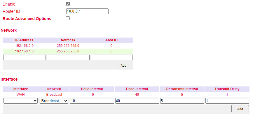
OSPF Configuration
Open Shortest Path First (OSPF) is a link-state routing protocol used mainly in large-scale networks to determine the shortest path for data packets.
Process Example: Establish OSPF routes between two routers to enable mutual LAN access.
Configure TK500v3_A:
Navigate to Network > OSPF.
Set “Router ID” in a compatible segment with TK500v3_B.
Announce routing entries for TK500v3_A through the “Network” tab.
Configure TK500v3_B:
Repeat similar steps to ensure settings align with TK500v3_A for successful route announcement.
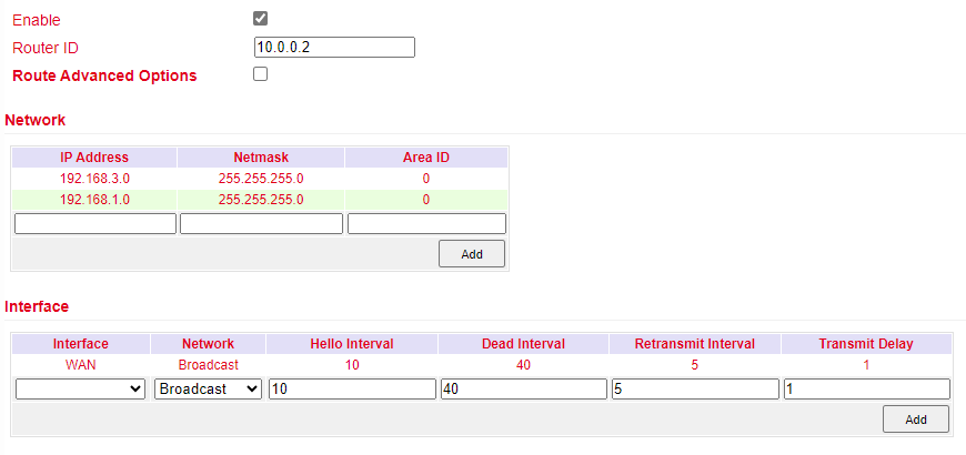
Verification:
OSPF setup is successful if PC1 and PC2 connected to TK500v3_A and TK500v3_B respectively can access each other.
Services Configuration
DHCP Service Configuration
DHCP (Dynamic Host Configuration Protocol) operates in a Client/Server mode, where the server allocates IP addresses dynamically to clients, simplifying network management.
To enable and configure DHCP Server:
Navigate to Services > DHCP Service.
DHCP Service Details
Parameter |
Description |
Default |
|---|---|---|
Enable DHCP |
Activates the DHCP service to dynamically allocate IP addresses. |
Enabled |
IP Pool Starting Address |
Sets the beginning of the IP range for dynamic allocation. |
192.168.2.2 |
IP Pool Ending Address |
Sets the end of the IP range for dynamic allocation. |
192.168.2.100 |
Lease Time |
Duration for which an IP address is allocated to a device before renewal is required. |
60 minutes |
DNS Server |
Specifies the DNS server address for client devices. |
192.168.2.1 |
Windows Name Server |
Sets the Windows name server for network name resolution. |
N/A |
Static DHCP Allocation |
Allows for the assignment of fixed IP addresses to specific MAC addresses. |
Up to 20 entries |
DNS Configuration
The Domain Name System (DNS) is crucial for converting user-friendly domain names into IP addresses that networks use to identify and locate computer services and devices. When a static IP is used on the WAN port, setting up DNS manually becomes necessary.
Navigation: Go to Service > Domain Name Service in the navigation tree to manage DNS settings.
DNS Settings Table
Parameter |
Description |
Default |
|---|---|---|
Primary DNS |
Specifies the primary DNS server IP address that the device should use. |
0.0.0.0 |
Secondary DNS |
Specifies a secondary DNS server IP address for redundancy. |
0.0.0.0 |
Disable local DNS server |
If enabled, prevents the device from passing the local DNS server address. |
Disabled |
DNS Relay Configuration
The TK500v3 can function as a DNS Agent, facilitating domain name resolution by relaying DNS requests and responses between DNS Clients and DNS Servers. This service is crucial when hosts are configured to automatically obtain DNS addresses.
Navigation: To configure DNS Relay, select Service > DNS Relay from the navigation menu.
DNS Relay Settings Table
Parameter |
Description |
Default |
|---|---|---|
Enable DNS Relay |
Activates the DNS Relay function to allow the router to act as an intermediary DNS agent. |
Enabled |
IP Address |
Specifies the IP address for a designated DNS relay entry. |
N/A |
Host |
Assigns a domain name to the corresponding IP address in the DNS relay. |
N/A |
Description |
Provides details or notes about the specific IP address and domain name pairing in the DNS relay setup. |
N/A |
Note: Enabling DHCP on the router will automatically activate the DNS Relay. Disabling DNS Relay requires turning off DHCP as well, as indicated in the system configuration. This integration ensures that DNS configurations are streamlined and automatically managed with DHCP settings.
DDNS Configuration
Dynamic Domain Name System (DDNS) is a service that maps a user’s dynamic IP address to a stable domain name, allowing others to connect using a memorable URL rather than an ever-changing IP address. This service is particularly useful for those hosting servers or remotely accessing systems at a non-static IP address.
Navigation: To configure DDNS, select Service > Dynamic Domain Name from the navigation tree.
DDNS Settings Overview
Parameter |
Description |
Default |
|---|---|---|
Service Type |
Specifies the DDNS service provider (e.g., DynDNS, No-IP). |
Disabled |
URL |
URL of the DDNS service provider. |
|
Username |
Your account username with the DDNS provider. |
N/A |
Password |
Your account password with the DDNS provider. |
N/A |
Host Name |
The domain name registered with the DDNS service. |
N/A |
Wildcard |
Enables wildcard DNS if supported by the provider. |
Disabled |
MX |
Specifies the Mail Exchange (MX) records if needed. |
N/A |
Backup MX |
Enables a backup for MX records. |
Disabled |
Force Update |
Forces the update of the DDNS record at each check interval. |
Disabled |
SNMP Overview
Network devices are often widely distributed across a network, making it challenging for administrators to manage and configure these devices onsite. Moreover, the complexity increases when these devices come from multiple vendors, each with its own set of management interfaces, such as different command line interfaces. Managing these devices in batches can be cumbersome and inefficient with traditional manual configuration methods, which are not only costly but also time-consuming.
To address these challenges, network administrators utilize the Simple Network Management Protocol (SNMP). SNMP enables remote configuration, management, and real-time monitoring of network devices, significantly enhancing operational efficiency.

Implementing SNMP in Your Network:
Configuration: Set up the Network Management System (NMS) on the management side and configure SNMP agents on the devices to be managed.
Functionality:
Monitoring: The NMS can gather status information from devices anywhere in the network at any time, enabling remote control and management.
Reporting: SNMP agents can quickly report the current status and any issues of the managed devices back to the NMS.
SNMP Versions:
SNMPv1 and SNMPv2c: These versions use community names for authentication, suitable for less complex and less secure environments.
SNMPv3: Offers enhanced security features, using usernames and passwords for authentication, ideal for networks requiring robust security measures.
To configure SNMP settings, navigate to the “Service>>SNMP” menu in your network management interface.
Parameter |
Description |
Default |
|---|---|---|
Enable |
Toggle to activate or deactivate the SNMP service. |
Disabled |
Version |
Select the SNMP protocol version appropriate for your network’s size and security requirements: |
v1 |
Contact Information |
Provide the contact details for the person or team managing the SNMP service. |
Empty |
Location Information |
Specify the physical or logical location of the device within the network. |
Empty |
Community Management |
Manage community strings which act as passwords for accessing SNMP data, important for versions v1 and v2c. |
|
Community Name |
Define custom names for SNMP communities. These names function as passwords in SNMPv1 and SNMPv2c. |
public and private |
Access Limit |
Set the access level for the Network Management System (NMS), restricting it to read-only or read-write permissions. |
Read-Only |
MIB View |
Choose which Management Information Base (MIB) objects are accessible to the NMS. Currently supports only the default view. |
defaultView |
Parameter |
Description |
Default |
|---|---|---|
User Group Management |
Manage user groups for SNMP access control. |
|
Groupname |
Define a unique name for the user group. Names can be up to 32 characters long. |
None |
Security Level |
Set the security level for the group. Options include: |
NoAuth/NoPriv |
Read-only View |
Configure access to allow viewing SNMP data without modification. Supports only the default view currently. |
defaultView |
Read-write View |
Allow both viewing and modification of SNMP data. Only the default view is supported currently. |
defaultView |
Inform View |
Define what SNMP notifications (informs) the group can receive. Currently, only the default view is supported. |
defaultView |
Usm Management |
Manage User-based Security Model (USM) settings. |
|
Username |
Specify a username for SNMPv3 authentication. Usernames can be 1 to 32 characters long. |
None |
Groupname |
Assign the user to an already configured user group. |
None |
Authentication |
Choose an authentication method for enhanced security: |
None |
Authentication Password |
Set a password for authentication. This is required if authentication is not set to ‘None’. Passwords must be 8 to 32 characters long. |
None |
Encryption |
Select an encryption method to secure SNMP communications: |
None |
Encryption Password |
Provide a password for encryption, necessary if encryption is enabled. Passwords must be 8 to 32 characters long. |
None |
SNMP Trap Configuration
SNMP Trap acts as a proactive notification mechanism within an SNMP-managed network. Unlike the regular polling method where the Network Management System (NMS) requests data from network devices, SNMP Traps allow devices to immediately report anomalies and errors directly to the NMS.
Navigation: To configure SNMP Traps, go to Service > SNMP Trap in the management interface.
SNMP Trap Settings
Parameter |
Description |
Default |
|---|---|---|
Trap Signal Level |
Defines the threshold for generating a trap. When this threshold is reached, the device sends a trap to the NMS. |
10 |
Destination Address |
Specifies the IP address of the NMS to receive the traps. |
None |
Security Name |
For SNMPv1 and SNMPv2c, enter the community name. For SNMPv3, enter the username. Supports up to 32 characters. |
None |
UDP Port |
Designates the UDP port through which traps are sent. Valid range is 1 to 65535. |
162 |
I/O Configuration
The I/O features of devices like the TK525L-IO-v3 allow for monitoring and controlling various physical inputs and outputs. This functionality is crucial for applications requiring real-time operational adjustments based on physical changes.
Navigation: Access this feature by selecting Service > I/O from the menu.
I/O Settings
Parameter |
Description |
Default |
|---|---|---|
I/O Mode |
Sets the mode of the I/O ports, either input or output. |
Output |
I/O Default Output Level |
Defines the default output state (low or high) when the port is configured as an output. |
Low |
Dry/Wet Contract |
Specifies the input type when the port is set to input mode, either Dry or Wet contact. |
Dry |
Input Triggered Report |
Enables reporting when the input condition is triggered. |
Disabled |
Trigger Edge |
Sets the sensitivity of the input trigger, either on the rising or falling edge. |
Falling Edge |
DTU RS232/RS485 Configuration
The DTU (Data Terminal Unit) functionality allows devices to transmit serial data directly to a server. This feature is available on all models except the TK525L-IO-v3.
DTU RS232/RS485 Basic Configuration
Parameter |
Description |
Default |
|---|---|---|
Enable |
Activates the serial port for data transmission. |
Disabled |
Serial type |
Specifies the type of serial port used, which cannot be altered. |
RS232 or RS485 |
Baudrate |
Configures the baud rate for the serial port. |
115200 |
Data Bits |
Sets the number of data bits in each character. |
8 |
Parity |
Chooses the parity bit setting for error checking. |
None |
Stop Bit |
Determines the number of stop bits to end a character. |
1 |
Software Flow Control |
Enables software control to prevent data loss. |
Disabled |
DTU Advanced Configuration
This section allows detailed settings for the protocol and connection specifics between the router and server.
Parameter |
Description |
Default |
|---|---|---|
DTU Protocol |
Sets the protocol used for transmitting DTU data. |
Transparent |
Protocol |
Configures the protocol type for the connection, such as TCP or UDP. |
TCP |
Mode |
Establishes the connection mode, like Client or Server. |
Client |
Frame Interval |
Specifies the interval between data frames. |
100 ms |
Serial Buffer Frames |
Sets how many frames are buffered before sending. |
4 |
Keep Alive Interval |
Time between signals sent to check the connection’s health. |
60 s |
Keep Alive Retry Time |
Number of attempts to reconnect after losing connection. |
5 |
Multi-Server Policy |
Policy for handling connections to multiple servers. |
Parallel |
Min Reconnect Interval |
Minimum time before attempting to reconnect. |
15 s |
Max Reconnect Interval |
Maximum time before attempting to reconnect. |
180 s |
DTU ID |
Unique identifier for the router in server communications. |
N/A |
Source IP |
Specifies the IP address the router uses when connecting to the server. |
Uses WAN IP if blank |
Source Port |
Specifies the port the router uses for outbound connections. |
Uses random port if blank |
DTU ID Report Interval |
Sets how often the DTU ID is reported to the server. |
0 |
DTU Serial Port Traffic Statistics |
Reports serial port traffic data to the monitoring interface. |
Disabled |
Multi Server Configuration
Allows for data transmission to multiple servers, enhancing redundancy and reliability of data communication.
Parameter |
Description |
Default |
|---|---|---|
Server Address |
IP address or hostname of the server to receive data. |
N/A |
Server Port |
Network port on the server designated to receive data. |
N/A |
SMS Configuration
SMS functionality enables remote management of the device through text commands, such as rebooting the device or manually dialing and disconnecting network connections. Set permissions for specific phone numbers and apply changes to activate this service.
Navigation: Access this feature by selecting Service > SMS from the navigation menu.
SMS Settings Overview
Parameter |
Description |
Default |
|---|---|---|
Enable |
Activates the SMS-based management features for the router. |
Disabled |
Status Query |
Defines the command text for querying the current operational status of the router. |
N/A |
Reboot |
Sets the command text to remotely reboot the router via SMS. |
N/A |
SMS Access Control Settings
Manage which phone numbers can interact with the router via SMS and define the actions these numbers are authorized to perform.
Parameter |
Description |
Default |
|---|---|---|
Default Policy |
Sets how incoming commands from unlisted numbers are handled (Accept or Block). |
Accept |
Phone Number |
Specifies a mobile number authorized to send SMS commands to the router. |
N/A |
Action |
Determines whether to accept or block SMS commands from the specified phone number. |
Accept |
Description |
Provides details about the rules set for SMS control, explaining the purpose or restrictions applied. |
Traffic Manager Configuration
The Traffic Manager is a crucial tool for monitoring and controlling data usage on the cellular interface of a router. This function is especially valuable for ensuring data limits are not exceeded, and requires the NTP function to be enabled for accurate timing.
Navigation: To access and configure the Traffic Manager, go to Services > Traffic Manager.
Overview of Traffic Manager Settings
Parameter |
Description |
Default |
|---|---|---|
Enable |
Activates the Traffic Manager to monitor and manage cellular data usage. |
Disabled |
Start Day |
Specifies the day each month when data usage tracking will begin. |
1 |
Monthly Threshold |
Sets a data usage limit for each month. If set to 0MB, no limit is enforced but data usage is still tracked. |
0MB |
When Over Monthly Threshold |
Determines the router’s response when monthly data usage exceeds the threshold: |
Only Reporting |
Last 24-Hours Threshold |
Sets a daily data usage limit for the past 24 hours. |
0KB |
When Over 24-Hours Threshold |
Specifies actions when data usage exceeds the 24-hour threshold. |
Only Reporting |
Advance |
Enables advanced settings for custom tracking and operations over specified durations. |
Disabled |
Alarm Settings
Alarm settings in the router ensure timely notifications in case of network anomalies. The router is capable of reporting alarms in various scenarios including system service faults, memory shortages, and connectivity changes across WAN, LAN, and cellular interfaces, among others. These settings help in proactive network management and troubleshooting.
Navigation: To configure alarms, go to Services > Alarm Manager.
Configuration Overview
Alarm Input: Select the types of alarms you want to monitor.
Alarm Output: Choose how you want to be notified about the alarms, such as via console notifications.
Firewall Configuration
The firewall in the router manages and controls data flow both inbound (from the Internet to the LAN) and outbound (from LAN to the Internet) based on various parameters like protocol type, IP addresses, etc. This is crucial for ensuring the security of both the router and the devices within the network.
Navigation: For basic firewall settings, go to Firewall > Basic Setup.
Basic Setup of Firewall
Parameter |
Description |
Default |
|---|---|---|
Default Filter Policy |
Choose whether to accept or block incoming and outgoing traffic by default. |
Accept |
Filter PING Detection from Internet |
Enable or disable filtering of PING requests from the Internet to enhance security. |
Disable |
Filter Multicast |
Toggle to allow or block multicast traffic, which can optimize network performance. |
Enable |
Defend DoS Attack |
Activate protection against Denial of Service attacks to safeguard network integrity. |
Enable |
SIP ALG |
Enable or disable the Application Layer Gateway for SIP protocol to assist in traversing NAT. |
Disable |
Network Data Filtering
Network data filtering allows for the customization of rules to control the data flows permitted or denied by the router.
Navigation: To configure data filtering, go to Firewall > Filtering on the navigation menu.
Access Control Settings
Parameter |
Description |
Default |
|---|---|---|
Enable |
Toggle to activate or deactivate filtering. |
Enable |
Protocol |
Choose the protocol for filtering: All, TCP, UDP, or ICMP. |
ALL |
Source Address |
Specify the originating IP address for the rule. |
0.0.0.0/0 |
Source Port |
Define the source port range for the rule. |
Not available |
Destination Address |
Enter the destination IP address for the rule. |
N/A |
Destination Port |
Set the destination port range for the rule. |
Not available |
Action |
Decide whether to accept or block packets based on the rule. |
Accept |
Log |
Enable logging to record events related to this access control rule in the system logs. |
Disable |
Description |
Provide a description for the rule, useful for later reference. |
N/A |
Device Access Filtering
Customize rules to manage data and access to the router more effectively.
Navigation: Access this feature by selecting Firewall > Device Access Filtering.
Device Access Control Settings
Parameter |
Description |
Default |
|---|---|---|
Enable |
Activate this feature to start filtering device access based on specified rules. |
Enable |
Protocol |
Select the protocol to filter: All, TCP, UDP, or ICMP. |
ALL |
Source |
Set the source IP address from which access is being controlled. |
0.0.0.0/0 |
Source Port |
Specify the source port from which the traffic originates. |
Not available |
Destination |
Define the destination IP address for the traffic. |
N/A |
Destination Port |
Set the destination port for incoming traffic. |
Not available |
Interface |
Choose the network interface through which the traffic will be filtered. |
All WANs |
Action |
Determine whether to accept or block traffic based on the specified conditions. |
Accept |
Log |
Enable logging for actions taken based on the device access rules. |
Disable |
Description |
Add a description for the rule to help in identifying the purpose of the rule. |
N/A |
Content Filtering Configuration
Content filtering allows for the restriction of access to specific URLs, ensuring network safety and compliance with organizational policies.
Navigation: Access this feature by selecting Firewall > Content Filtering from the navigation menu.
Content Filtering Settings
Parameter |
Description |
Default |
|---|---|---|
Enable |
Activates the content filtering function. |
Enable |
URL |
Specifies the URL to be blocked or restricted. |
N/A |
Action |
Determines whether to block or allow access to the specified URL. |
Block |
Log |
Enables logging of actions taken based on content filtering rules for audit and review. |
Disable |
Description |
Provides a brief explanation or note about the specific content filtering rule for reference. |
N/A |
Port Mapping Configuration
Port mapping, also known as virtual server setting, allows external hosts to access services on private network hosts through specific ports.
Navigation: To configure port mapping, go to Firewall > Port Mapping.
Port Mapping Settings
Parameter |
Description |
Default |
|---|---|---|
Enable |
Enables the port mapping function to forward specific external traffic to internal hosts. |
Enable |
Protocol |
Selects the protocol type for the mapping (TCP, UDP, or both). |
TCP |
Source |
Specifies the allowed source IP address range for incoming connections. |
0.0.0.0/0 |
Service Port |
Defines the external port number through which traffic is received. |
8080 |
Internal Address |
Specifies the IP address of the internal host that will receive the traffic. |
N/A |
Internal Port |
The port on the internal host that the service runs on. |
8080 |
Log |
Activates logging for the port mapping configuration to track usage and access. |
Disable |
External Interface |
(Optional) Sets a specific external network interface for the mapping. |
N/A |
External Address |
(Optional) Designates a specific external IP address or tunnel for the mapping. |
N/A |
Description |
Allows for a detailed description of what the port mapping rule is intended for. |
N/A |
Virtual IP Mapping Configuration
Virtual IP Mapping allows both the router and the internal host to correspond with a virtual IP, facilitating external access to internal hosts without changing the internal IP configuration. This is particularly useful in conjunction with VPN setups.
Navigation: Access this setting by selecting Firewall > Virtual IP Mapping.
Virtual IP Mapping Settings
Parameter |
Description |
Default |
|---|---|---|
Enable |
Activates the Virtual IP Mapping feature. |
Enable |
Virtual IP Address |
Sets the virtual IP that will represent the internal host externally. |
N/A |
Real IP |
Specifies the actual internal IP address corresponding to the virtual IP. |
N/A |
Range of Source Address |
Defines the allowable external IP address range that can access this mapping. |
N/A |
Log |
Enables logging of activities related to the virtual IP for monitoring and troubleshooting purposes. |
Disable |
Description |
Provides a brief explanation of the virtual IP setup for easy reference. |
N/A |
DMZ Configuration
The DMZ (Demilitarized Zone) allows external systems to access all ports on an internal device, ideal for hosting servers that need to be accessible from the internet.
Navigation: To configure DMZ settings, go to Firewall > DMZ.
DMZ Settings
Parameter |
Description |
Default |
|---|---|---|
Enable DMZ |
Enables or disables the DMZ functionality. |
Disable |
DMZ Host |
Specifies the internal IP address of the host that all inbound connections should be sent to. |
N/A |
Source Address Range |
Defines the range of external IP addresses allowed to interact with the DMZ host. |
N/A |
Interface |
Selects the external interface through which DMZ traffic will be routed. |
N/A |
MAC-IP Binding
MAC-IP Binding ensures that only specified devices can access the network, enhancing security by linking MAC addresses to specific IP addresses.
Navigation: Configure this by selecting Firewall > MAC-IP Binding.
MAC-IP Binding Settings
Parameter |
Description |
Default |
|---|---|---|
MAC Address |
Specifies the MAC address to bind. |
00:00:00:00:00:00 |
IP Address |
Assigns a specific IP address to the MAC address specified. |
192.168.2.2 |
Description |
Allows for a description to keep track of the purpose and details of the MAC-IP binding rule. |
N/A |
NAT Configuration
NAT (Network Address Translation) allows private IP addresses to be translated into public IP addresses, enabling devices on a local network to access the internet or external networks.
Navigation: To configure NAT, go to Firewall > NAT in the navigation menu.
NAT Settings
Parameter |
Description |
Default |
|---|---|---|
Enable |
Enables or disables NAT functionality. |
Enable |
Type |
Selects the type of NAT: SNAT (Source NAT) or DNAT (Destination NAT). |
SNAT |
Protocol |
Specifies the protocol used (TCP, UDP, etc.). |
TCP |
Source IP |
Defines the source IP range that NAT will apply to. |
0.0.0.0/0 |
Source Port |
Sets the source port range for the NAT rule. |
N/A |
Destination |
Specifies the destination IP for the NAT rule. |
0.0.0.0/0 |
Destination Port |
Sets the destination port range for the NAT rule. |
N/A |
Interface |
Indicates the network interface used for NAT. |
N/A |
Translated Address |
Defines the new IP address to translate to when the rule matches. |
0.0.0.0 |
Translated Port |
Sets the new port to translate to when the rule matches. |
N/A |
QoS and Bandwidth Management
QoS (Quality of Service) manages and prioritizes network traffic, ensuring that critical applications receive the bandwidth they need.
Navigation: Access this feature by selecting QoS > Bandwidth Control.
IP Bandwidth Limit Settings
Parameter |
Description |
Default |
|---|---|---|
Enable |
Activates bandwidth control. |
Disable |
Download bandwidth |
Sets the total available download bandwidth. |
1000kbit/s |
Upload bandwidth |
Sets the total available upload bandwidth. |
1000kbit/s |
Control port of flow |
Chooses the interface for bandwidth control (CELLULAR/WAN). |
CELLULAR |
Host Download Bandwidth |
Enables individual download bandwidth settings per IP. |
Enable |
IP Address |
Specifies the IP address to which the rule applies. |
N/A |
Guaranteed Rate (kbit/s) |
Sets the guaranteed bandwidth rate for the specified IP. |
1000kbit/s |
Priority |
Assigns a priority level (Low, Medium, High). |
Medium |
Description |
Provides details about the bandwidth control setting. |
N/A |
VPN Configuration
VPN (Virtual Private Network) serves as a method to establish a private network across a public network, enabling secure and private data communication.
Core Attributes of VPN:
Private: VPNs provide an exclusive environment for their users. This privacy means that data within the VPN is safeguarded against unauthorized access, ensuring that only authorized users can view or interact with the network.
Virtual: Despite utilizing the public internet, a VPN maintains the characteristics of a private network. This setup allows users to operate as if they are connected to a private network, enhancing security over potentially insecure public networks.
VPNs are instrumental in securely connecting remote users, branch offices, and partners to an organization’s main network. This setup facilitates the secure and reliable transmission of sensitive data across internet connections.
The diagram below illustrates the concept of a VPN, showing how remote connections can securely tap into central network resources through encrypted communications that traverse public networks.
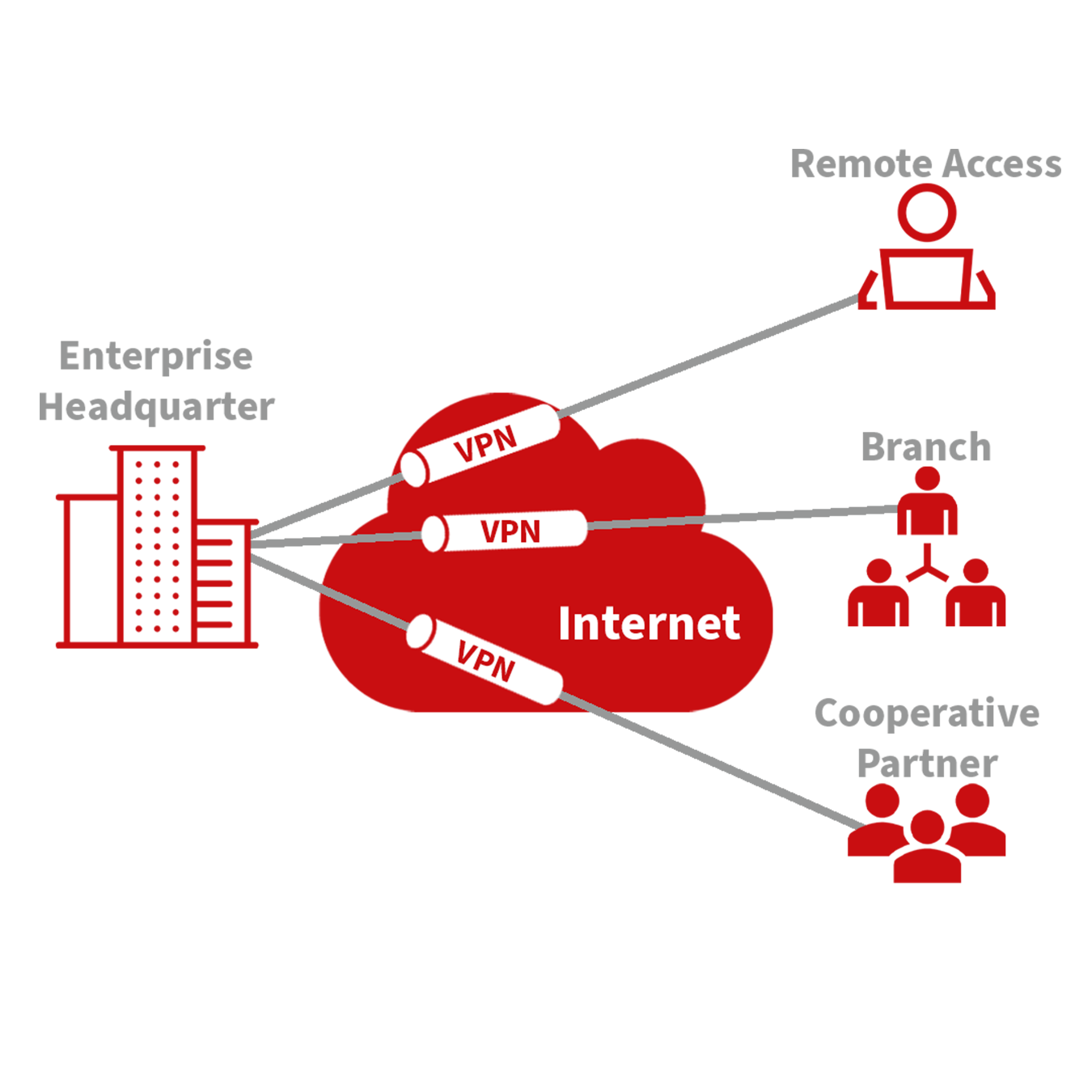
Fundamental Principle of VPN
The fundamental principle of a VPN (Virtual Private Network) is based on tunneling technology, which encapsulates VPN messages within a tunnel to establish a private data transmission channel over a public network. This setup enables secure and transparent message transmission across the VPN backbone.
Tunneling involves wrapping one protocol’s message within another protocol. The encapsulation protocol can also be nested within additional encapsulation protocols. For users, the VPN tunnel functions like a logical extension of a traditional PSTN or ISDN link, mimicking the behavior of a physical network connection. This method allows for secure communications as if they were occurring over a private, dedicated line, despite traversing a public infrastructure.
IPSec Settings
The majority of online data is transmitted in plaintext, exposing sensitive information such as passwords and banking details to potential theft, tampering, and malicious cyber attacks. Implementing IPSec enhances network security by protecting data transmissions and reducing the risk of information exposure.
IPSec, developed by the Internet Engineering Task Force (IETF), is a suite of protocols designed to secure internet communications at the IP level. It ensures data authenticity, encrypts communications, maintains data integrity, and provides anti-replay functions, effectively safeguarding data against unauthorized access and leaks.
This protocol suite includes Authentication Headers (AH), Encapsulating Security Payloads (ESP), and Internet Key Exchange (IKE), which collectively secure data flows between various entities such as hosts, gateways, and between host and gateway. AH and ESP protocols provide essential security features, while IKE facilitates the exchange of cryptographic keys.
IPSec enables the establishment of bi-directional security associations through IPSec peer pairs, creating secure, interoperable tunnels for safe data transmission across the internet.
To configure IPSec settings:
Navigate to the VPN>>IPSec Settings section of the system menu.
You can adjust the logging level to monitor the IPSec activities effectively:
Normal: Logs key events only.
Debug: Provides detailed logs useful for debugging.
Data: Logs all IPSec activities for comprehensive monitoring.
IPSec Tunnels Configuration
Navigate to the VPN>>IPSec Tunnels section in the menu to add and configure IPSec tunnels, ensuring secure data transmission between specified networks.
IPSec Tunnels |
||
|---|---|---|
Function Description: Configure IPSec tunnels for secure communication channels. |
||
Parameters |
Description |
Default |
Show Advanced Options |
Toggle to reveal advanced configuration options. |
Disabled (Enable to modify) |
Tunnel Name |
Assign a custom name to the tunnel. |
IPSec_tunnel_1 |
Destination Address |
Specify the endpoint IP address or domain name. |
0.0.0.0 |
IKE Version |
Choose between IKEv1 or IKEv2 based on compatibility. |
IKEv1 |
Startup Modes |
Define how the tunnel initiates: automatically, on-demand, passively, or manually. |
Auto Activated |
Restart WAN when failed |
Auto-restart the WAN interface if the tunnel fails. |
Enabled |
Negotiation Mode (IKEv1) |
Choose between Main Mode and Aggressive Mode. |
Main Mode |
IPSec Protocol |
Select either ESP or AH protocol for security. |
ESP |
IPSec Mode |
Opt between Tunnel Mode or Transport Mode. |
Tunnel Mode |
VPN over IPSec |
Configure for additional security layers like L2TP or GRE over IPSec. |
None |
Tunnel Type |
Set the connection type, e.g., Host-Host, Host-Subnet, etc. |
Subnet-Subnet |
Local Subnet Address |
Local network address to include in the tunnel. |
192.168.2.1 |
Local Subnet Mask |
Network mask for the local subnet. |
255.255.255.0 |
Peer Subnet Address |
Address of the remote subnet involved in the tunnel. |
0.0.0.0 |
Peer Subnet Mask |
Network mask for the remote subnet. |
255.255.255.0 |
IKE Policy |
Define encryption and hash algorithms for Phase I. |
3DES-MD5-DH2 |
IKE Lifetime |
Duration before re-establishing the IKE connection. |
86400 seconds |
Local ID Type |
Identity type for the local endpoint (IP Address, User FQDN). |
IP Address |
Remote ID Type |
Identity type for the remote endpoint. |
IP Address |
Authentication Type |
Choose between a pre-shared key or a digital certificate. |
Shared key |
Key |
Specify the encryption key if using a pre-shared key. |
N/A |
XAUTH Mode |
Enable or disable Extended Authentication (XAUTH). |
Disabled |
Phase II Parameters |
Settings for the secure exchange of data during the second phase of IPSec negotiations. |
|
IPSec Policy |
Set policies for data integrity and encryption for Phase II. |
3DES-MD5-96 |
IPSec Lifetime |
Time before the IPSec tunnel re-establishes. |
3600 seconds |
Perfect Forward Secrecy (PFS) |
Enable PFS to enhance security by generating a unique new key for each session. |
Disabled (match server settings) |
Link Detection Parameters |
Configure settings to detect link status and health. |
|
DPD Interval |
Duration between “Dead Peer Detection” signals. |
60 seconds |
DPD Timeout |
Time to consider the connection dead after a missed DPD. |
180 seconds |
ICMP Detection Server |
Set a server to use for ICMP-based link detection. |
N/A |
ICMP Detection Interval |
Time between ICMP echo requests used for link monitoring. |
60 seconds |
ICMP Detection Timeout |
Timeout for ICMP detection to consider the link down. |
5 seconds |
ICMP Detection Retries |
Number of retry attempts for ICMP detection before considering the link failed. |
10 |
The security levels of encryption algorithms AES, 3DES, and DES increase respectively. AES provides the highest security but has more complex implementation and slower computational speeds. 3DES offers a balance between security and speed, while DES, though less secure, meets basic security needs and operates faster.
GRE Tunnels
Generic Routing Encapsulation (GRE) is a protocol that encapsulates various network layer protocols within a virtual tunnel. This tunneling protocol is often utilized in Virtual Private Networks (VPNs) to create a secure channel for data transmission, allowing for the seamless transfer of encapsulated data packets across diverse network environments. Essentially, GRE facilitates the creation of private communication channels over public networks by encapsulating a wide range of protocol packet types inside IP tunnels. This encapsulation and the subsequent decapsulation occur at the endpoints of the GRE tunnel. The concept of GRE tunneling is illustrated in the diagram below, which demonstrates how GRE provides a transparent and protected data pathway across networks.
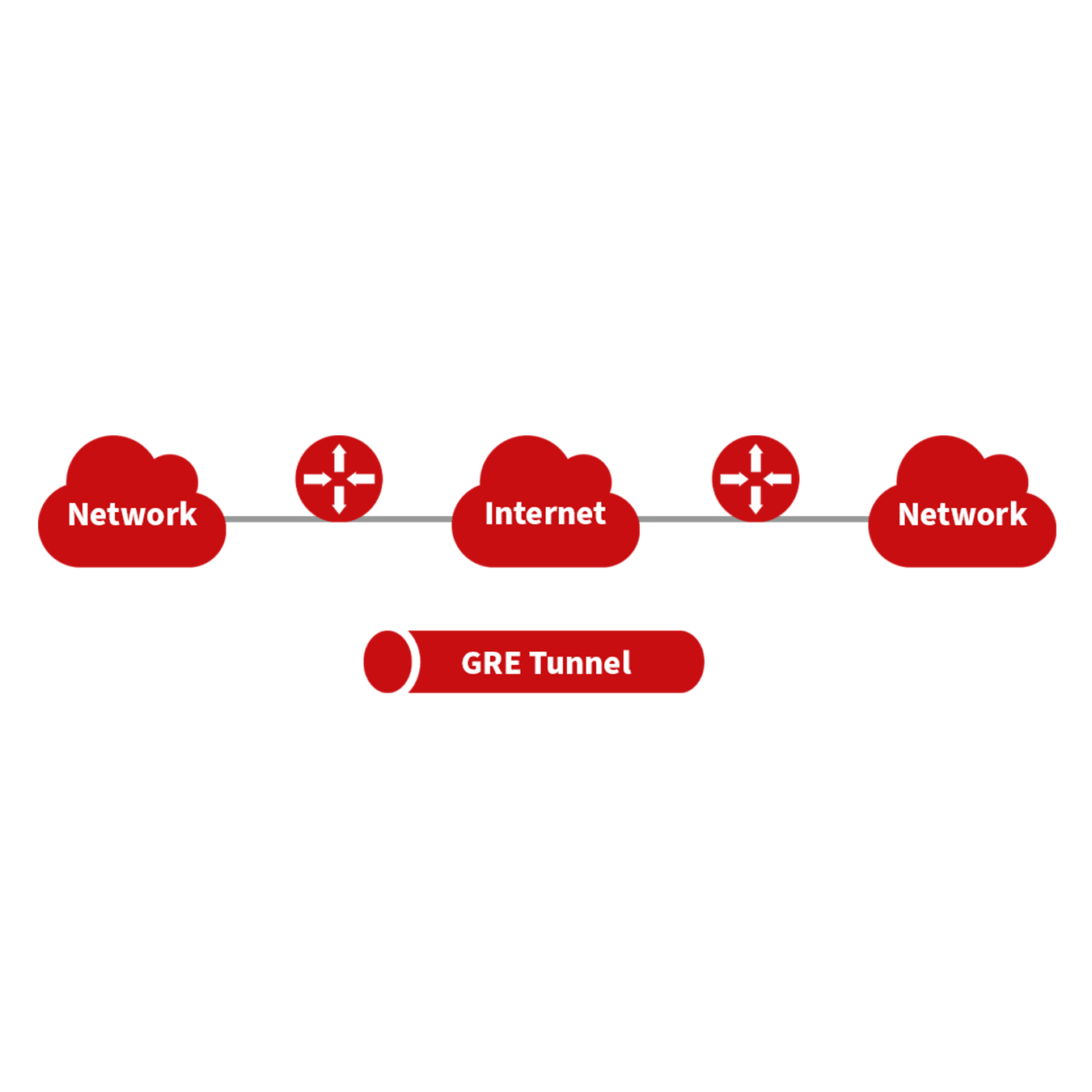
With the widespread use of IPv4, GRE (Generic Routing Encapsulation) is utilized to transmit network layer protocol messages over an IPv4 network by encapsulating these messages. This approach effectively addresses the challenges of transmitting data between different network types.
GRE Tunnel Usage Scenarios:
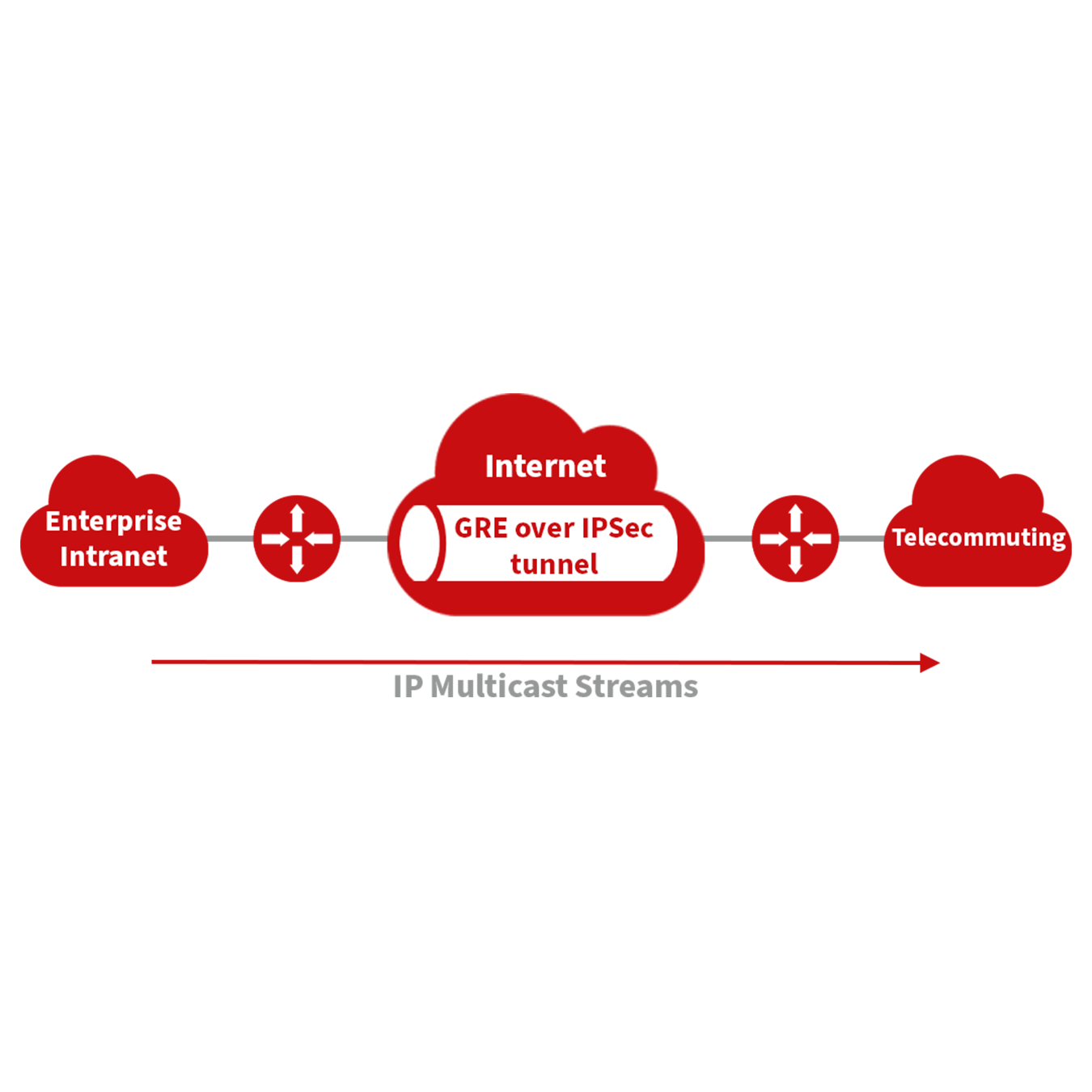
Multicast Data Transmission: GRE tunnels can transmit multicast data packets as if they were being sent over a standard network interface. This capability is significant because IPSec alone cannot encrypt multicast data.
Routing Unsupported Protocols: When a specific protocol does not support routing, GRE tunnels can be used to encapsulate and transport these protocols across different network segments.
Connecting Disparate Networks: GRE tunnels are ideal for connecting two similar network segments that operate under different IP addresses, facilitating seamless data exchange.
Application of GRE with IPSec for Multicast Data Security: GRE is adept at encapsulating multicast data for tunnel transmission. However, since IPSec cannot directly encrypt multicast data due to its design to protect only unicast transmissions, GRE tunnels can be first established to encapsulate the multicast data. Afterward, the encapsulated data can be encrypted using IPSec. This method ensures the secure transmission of multicast data across an IPSec tunnel. This technique combines GRE’s flexibility in handling different data types with IPSec’s robust security features, thus providing a comprehensive security solution.
From the navigation menu, select VPN > GRE Tunnels to access the “GRE Tunnels” configuration page.
GRE Tunnels |
||
|---|---|---|
Function Description: Set up GRE tunnels for network encapsulation and secure data transport. |
||
Parameters |
Description |
Default |
Enable |
Activate GRE tunneling. |
Enabled |
Name |
Assign a name for the GRE tunnel. |
tun0 |
Local Virtual IP |
Specify the local virtual IP address. |
Configured IP |
Destination Address |
Enter the IP address of the remote endpoint. |
Configured IP |
Peer Virtual IP |
Define the virtual IP address of the peer. |
Configured IP |
Peer Subnet Address |
Set the IP address of the peer subnet. |
Configured Subnet |
Peer Subnet Mask |
Specify the subnet mask for the peer network. |
255.255.255.0 |
Key |
Enter a key for authentication in the GRE tunnel. |
Specified Key |
NAT |
Enable Network Address Translation if required. |
Disabled |
Description |
Provide a description for the GRE tunnel configuration. |
Custom description |
L2TP Client
L2TP, a pivotal VPN technology, extends the functionality of PPP by allowing remote access to corporate networks. It is particularly useful for branch offices and traveling employees to connect securely to the main corporate network.
Using L2TP, remote users can establish a tunnel from their location to the enterprise headquarters over the internet, using the PPP framework to manage the connection. This tunnel allows for secure, encrypted communications between the remote user and the corporate network. L2TP itself does not include encryption mechanisms, so it is typically paired with IPsec to ensure data security.
Primary Use: Allows employees at branch offices or on the road to securely access corporate network resources via a virtual tunnel established over public networks.
The typical setup involves establishing an L2TP tunnel that encapsulates PPP frames, with IPsec providing the necessary encryption. This setup ensures that remote connections to the corporate network are secure and private.

To access the L2TP Client configuration, go to the VPN section in the navigation tree, select “L2TP Client,” and click “add.”
L2TP Client Configuration
Field |
Description |
Default Setting |
|---|---|---|
Enable |
Toggle to activate the L2TP client. |
Disabled |
Tunnel Name |
Assign a descriptive name to the L2TP client tunnel. |
L2TP_tunnel_1 |
L2TP Server |
Enter the address of the L2TP server. |
None |
Username |
Specify the username required for server authentication. |
None |
Password |
Input the password corresponding to the username. |
None |
Server Name |
Provide the name of the server. |
l2tpserver |
Startup Modes |
Choose how the tunnel initiates: automatically, manually, etc. |
Auto Activated |
Authentication Method |
Select the protocol for authentication, such as CHAP or PAP. |
CHAP |
Enable Challenge Secrets |
Enable additional security measures if required. |
Disabled |
Challenge Secret |
Enter the challenge secret if the above option is enabled. |
None |
Local IP Address |
Assign a local IP address for the connection if required. |
None |
Remote IP Address |
Specify the remote IP address you are connecting to. |
None |
Remote Subnet |
Define the remote subnet address. |
None |
Remote Netmask |
Set the subnet mask for the remote network. |
255.255.255.0 |
Link Detection Interval |
Set the interval for checking the link status. |
60 seconds |
Max Retries for Link Detection |
Determine the maximum retry attempts for link detection. |
5 |
Enable NAT |
Toggle Network Address Translation if needed for this connection. |
Disabled |
MTU |
Set the maximum transmission unit size. |
1500 bytes |
MRU |
Set the maximum receive unit size. |
1500 bytes |
Enable Debug |
Activate debug mode to capture detailed system logs. |
Disabled |
Expert Option |
Advanced settings not recommended for typical users. |
None |
To configure the PPTP Client, navigate to the VPN section in the navigation tree, select “PPTP Client,” and click “add.”
PPTP Client Configuration
Field |
Description |
Default Setting |
|---|---|---|
Enable |
Toggle to activate the PPTP client. |
Disabled |
Tunnel Name |
Assign a name for the PPTP tunnel. |
PPTP_tunnel_1 |
PPTP Server |
Specify the server address for the PPTP connection. |
None |
Username |
Enter the username for server authentication. |
None |
Password |
Input the password for server access. |
None |
Startup Modes |
Choose how the tunnel initiates (automatically, manually, etc.). |
Auto Activated |
Authentication Method |
Select the authentication protocol to be used (CHAP, PAP, etc.). |
Auto |
Local IP Address |
Set a local IP address for the connection. |
None |
Remote IP Address |
Specify the remote IP address for the connection. |
None |
Remote Subnet |
Define the remote subnet address. |
None |
Remote Netmask |
Set the subnet mask for the remote network. |
255.255.255.0 |
Link Detection Interval |
Configure the interval for checking the connection status. |
60 seconds |
Max. Retries for Link Detection |
Determine the maximum retry attempts for link detection. |
5 |
Enable NAT |
Toggle Network Address Translation for this connection. |
Disabled |
MTU |
Set the maximum transmission unit size. |
1500 bytes |
MRU |
Set the maximum receive unit size. |
1500 bytes |
Enable Debug |
Activate debug mode to capture detailed logs. |
Disabled |
Set Expert Option |
Access advanced settings (not generally recommended for typical users). |
None |
OpenVPN Overview
OpenVPN supports various methods for verifying user identities during VPN setup, including the use of preset private keys, third-party certificates, or username/password combinations. It leverages the OpenSSL encryption library and SSLv3/TLSv1 protocols extensively to ensure robust security.
When using OpenVPN, if a user needs to connect to a remote virtual address compatible with a virtual network card, the operating system routes either data packets (in TUN mode) or data frames (in TAP mode) to the virtual network card. Once received, the OpenVPN service processes this data and sends it across the internet using a socket connection. This data is then received by a corresponding service program at the destination, processed, and sent on to the destination virtual network card. This process enables application software to receive and handle data, allowing for secure bidirectional data transmission.
To configure or modify OpenVPN settings, navigate to “VPN>>OpenVPN” on your system’s navigation tree, enter the “OpenVPN” page, and click “Add” to start the setup process.
Here’s a refined version of the OpenVPN configuration table, improving clarity and usability:
OpenVPN Configuration |
Description |
Default Settings |
|---|---|---|
Tunnel Name |
Designate a unique name for the OpenVPN tunnel. Cannot be altered by the system. |
OpenVPN_T_1 |
Enable |
Toggle to activate or deactivate the OpenVPN tunnel. |
Enabled |
Mode |
Specify the operational mode: Client or Server. |
Client |
Protocol |
Choose the communication protocol: UDP or ICMP. |
UDP |
Port |
Assign the port for OpenVPN traffic. |
1194 |
OpenVPN Server |
Enter the address of the OpenVPN server. |
Not applicable (N/A) |
Authentication Method |
Select the method of authentication: Pre-shared key, Username/Password, Digital Certificate, or Multiple Client Digital Certificates combined with Username Authentication. |
Not applicable (N/A) |
Local IP Address |
Set the local IP address for the VPN connection. |
Not applicable (N/A) |
Remote IP Address |
Specify the remote IP address for the VPN connection. |
Not applicable (N/A) |
Remote Subnet |
Define the remote subnet address for networking. |
Not applicable (N/A) |
Remote Netmask |
Set the netmask for the remote subnet. |
255.255.255.0 |
Link Detection Interval |
Configure the interval for checking the VPN link’s status. |
60 seconds |
Link Detection Timeout |
Set the timeout period for link detection. |
315 seconds |
Enable NAT |
Toggle to enable or disable Network Address Translation (NAT). |
Enabled |
Enable LZO Compression |
Toggle to enable or disable LZO compression for data efficiency. |
Enabled |
Encryption Algorithms |
Choose the encryption algorithm: Blowfish (128), DES (128), 3DES (192), AES (128, 192, 256). |
Blowfish (128) |
MTU (Maximum Transmission Unit) |
Set the maximum size of data packets transmitted. |
1500 bytes |
Maximum Fragment Size |
Define the maximum size for fragmented data packets. |
Not applicable (N/A) |
Debug Level |
Set the verbosity of logs: Error, Warning, Information, or Debug. |
Warning |
Interface Type |
Choose the type of virtual network interface: TUN (network layer) or TAP (link layer). |
TUN |
Expert Option (not recommended) |
Set advanced options that are not typically recommended for general users. |
Not applicable (N/A) |
OpenVPN Advanced Configuration
Navigate through the menu by selecting “VPN > OpenVPN Advanced” to access the OpenVPN Advanced settings interface.
OpenVPN Advanced Settings |
Description |
Default Setting |
|---|---|---|
Enable Client-to-Client (Server Mode Only) |
Toggle to allow direct client-to-client connections |
Disabled |
Client Management |
||
Enable Client Management |
Activate management of client connections |
Enabled |
Tunnel Name |
Specify the name of the tunnel |
OpenVPN_T_1 |
Username/CommonName |
Enter the username or common name for authentication |
Not Applicable (N/A) |
Password |
Set a password for client authentication |
Not Applicable (N/A) |
Client IP (4th byte must be 4n+1) |
Assign a static IP address for the client |
Not Applicable (N/A) |
Local Static Route |
Define static routes on the local network |
Not Applicable (N/A) |
Remote Static Route |
Set static routes on the remote network |
Not Applicable (N/A) |
WireGuard Tunnels
WireGuard represents the next generation of VPN technology, emphasizing superior efficiency and enhanced security through advanced encryption.
To set up a WireGuard tunnel, navigate to the VPN section and select “WireGuard Tunnels” from the navigation tree. There, you can manage the configuration and monitor the VPN status.
WireGuard Tunnels |
Description |
Default Setting |
|---|---|---|
Tunnel Name |
Designate a unique name for the WireGuard tunnel. |
WireGuard_tun_1 |
Enable |
Toggle to activate or deactivate the tunnel. |
Enabled |
Address |
Specify the local virtual IP address and subnet mask in CIDR format, e.g., 192.168.2.1/24. |
Not Applicable |
Shared Connection (NAT) |
Choose whether local devices can access the Internet through this tunnel: Enabled allows access, Disabled blocks access. |
Enabled |
Listening Port |
Specify the listening port for the VPN. If left blank, the default port (51820) is used. Ensure unique ports for different tunnels. |
51820 |
Private Key |
Enter the private key generated by WireGuard. |
Not Applicable |
MTU |
Set the Maximum Transmission Unit for VPN packets. |
1500 |
Peer Parameters |
||
Name |
Assign a name to the VPN peer. |
Not Applicable |
End Point |
Define the remote peer’s IP address and port, e.g., 1.2.3.4:51820. |
Not Applicable |
Allowed IPs |
Restrict which local addresses can route through this tunnel. |
0.0.0.0/0 (all) |
Public Key |
Enter the public key generated by WireGuard corresponding to the local private key. |
Not Applicable |
Pre-shared Key (Optional) |
Additional security can be provided by entering a pre-shared key generated by WireGuard. |
Not Applicable |
Persistent Keepalive |
Set an interval for sending keepalive packets if NAT is enabled; setting it to 0 disables this feature. |
25 |
WireGuard Key Generator |
|---|
Utilize the Generate button to create private keys, public keys, or pre-shared keys directly in WireGuard. Input a private key to generate its corresponding public key. Private keys are used in local tunnel settings, whereas public keys are used in peer settings. |
ZeroTier VPN
ZeroTier VPN enables users to establish a network that connects all client devices, allowing seamless inter-device communication. ZeroTier supports two types of networks: planet and moon. To use a planet network, users must first register and create a VPN network at ZeroTier’s official website. A moon network, on the other hand, is a private VPN network created and managed by the user.
Navigate through the VPN section and select “ZeroTier VPN” from the navigation tree to access the configuration page.
Parameters |
Description |
Default |
|---|---|---|
Enable |
Toggle to activate or deactivate ZeroTier VPN. |
Disabled |
Tunnel Name |
Assign a name to the local VPN tunnel for identification. |
Not Applicable |
Network Type |
Choose between a ‘planet’ or ‘moon’ network type. |
Planet |
Network ID |
Enter the 16-character network ID to connect to the VPN. |
Not Applicable |
Certificate Management
Navigate through the VPN section and select “Certificate Management” from the navigation tree to access the certificate management interface.
Parameters |
Description |
Default |
|---|---|---|
Enable SCEP (Simple Certificate Enrollment Protocol) |
Toggle to activate SCEP. |
Disabled |
Protect Key |
Enter a protection key for certificate security. |
Not Applicable |
Confirm Protect Key |
Re-enter the protection key to confirm. |
Not Applicable |
Force Re-enrollment |
Enable to force certificate re-enrollment. |
Disabled |
Request Status |
Displays the current status of certificate enrollment. Cannot be modified. |
Ready to refile an enrollment |
Server URL |
Enter the URL of the SCEP server. |
Not Applicable |
Common Name |
Set the common name for the certificate. |
Not Applicable |
FQDN (Fully Qualified Domain Name) |
Enter the fully qualified domain name. |
Not Applicable |
Organizational Units |
Specify organizational units, such as ‘Unit 1’ and ‘Unit 2’. |
Not Applicable |
Domain |
Define the domain name associated with the certificate. |
Not Applicable |
Serial Number |
Assign a serial number to the certificate. |
Not Applicable |
Challenge |
Set a challenge password for additional security during certificate enrollment. |
Not Applicable |
Confirm Challenge |
Confirm the challenge password. |
Not Applicable |
RSA Key Length |
Choose the RSA key length, e.g., 1024 bits. |
1024 |
Poll Interval |
Set the frequency at which the system checks for certificate status updates. |
60 seconds |
Poll Timeout |
Define how long the system should wait for a response during the certificate status check. |
3600 seconds |
Import/Export Certificate |
Manage certificate files by importing or exporting to and from the router. |
|
Import CA Certificate |
Import a CA certificate directly to the router. |
Not Applicable |
Export CA Certificate |
Export the CA certificate from the router to a local computer. |
Not Applicable |
Import/Export Other Certificates |
Manage other types of certificates such as public keys, private keys, and CRLs. |
Not Applicable |
Note: Ensure the router’s clock is synchronized with real-time to prevent issues with certificate validation.
Tools
Ping Tool Configuration
To perform a network ping test, navigate to Tools >> Ping Detection in the navigation menu and access the “Ping Detection” page.
Parameters |
Description |
Default |
|---|---|---|
Host Address |
Enter the IP address or hostname for the ping test. |
Not Applicable |
Ping Count |
Specify the number of ping requests to send. |
4 |
Packet Size |
Define the size of each ping packet in bytes. |
32 bytes |
Advanced Options |
Access additional ping parameters. |
Not Applicable |
Traceroute Configuration
To conduct a traceroute analysis, navigate through the menu to Tools >> Traceroute, and access the “Traceroute” page.
Parameters |
Description |
Default |
|---|---|---|
Host Address |
Specify the IP address or hostname for the traceroute destination. |
Not Applicable |
Maximum Hops |
Determine the maximum number of hops traceroute will follow. |
20 |
Timeout |
Set the timeout duration for each traceroute packet. |
3 seconds |
Protocol |
Choose between ICMP or UDP for the traceroute queries. |
UDP |
Advanced Options |
Access additional settings for the traceroute command. |
Not Applicable |
Link Speed Test
Navigate through the menu by selecting “Tools>>Link Speed Test” to access the “Link Speed Test” page. Here you can test your network connection speed by uploading or downloading a file and viewing the results in the log.
TCPDUMP
For network packet analysis, go to “Tools>>TCPDUMP” on the navigation menu to reach the TCP dump interface.
Parameters |
Description |
Default |
|---|---|---|
Interface |
Choose the network interface for packet capture. |
ANY |
Capture Count |
Number of packets to capture before stopping. |
10 |
Advanced Options |
Access additional settings for packet capture. |
Not Applicable |
Application
SMART EMS Configuration
Navigate to Application >> Smart-EMS on the interface to access the “Smart-EMS” configuration page. This section allows you to set up router onboarding to SMART EMS.
Parameters |
Description |
Default |
|---|---|---|
Server URL |
Specify the server URL for SMART EMS. |
Not Applicable |
Username |
Enter the username for server access. |
Not Applicable |
Password |
Enter the password for server access. |
Not Applicable |
Contact Interval |
Set the interval for communication checks. |
Not Applicable |
Send Running Config |
Toggle the sending of current configuration settings. |
Disabled |
Write Startup |
Enable saving configurations to be run at startup. |
Disabled |
Status Overview
System Status
Navigate to the “System” page by selecting Status >> System from the navigation tree. This page offers detailed system statistics, including the router’s name, model, serial number, description, current firmware version, bootloader version, router and PC time, uptime, CPU load, and memory usage. For time synchronization with the host system, use the
Modem Information
For modem details, go to Status >> Modem. This section provides essential information about the modem’s operation, including connection status, signal strength, registration status, and identifiers such as the IMEI (ESN) code, IMSI code, LAC, and cell ID. You can also configure modem parameters from this page.
Traffic Statistics
Access the “Traffic Statistics” page by selecting Status >> Traffic Statistics. It displays comprehensive traffic data on the dial-up interface, detailing traffic received and transmitted over various periods—last month, yesterday, and the last hour.
DTU Status
This function is available only for TK500v3 serial type devices. To check the status of serial connections, navigate to Status >> DTU.
Alarm Monitoring
Visit the “Alarm” page by selecting Status >> Alarm. This page allows you to view, clear, or acknowledge alarms since the device was powered on. Alarms are presented with their current state (Raised, Confirmed) and are categorized by severity levels:
EMERG: Critical errors causing system reboot.
CRIT: Unrecoverable errors affecting device operation.
WARN: Issues affecting system functionality.
NOTICE: Situations impacting system performance.
INFO: Logs of normal operational events.
System Status Overview
WLAN Connection Status
To view the WLAN connection status, navigate to Status >> WLAN. This page provides detailed information on the wireless network, including the channel, SSID, BSSID, security settings, signal strength (as a percentage), operational mode, and current status. This overview helps you monitor and troubleshoot your wireless connections effectively.
Network Connections
Access network connections details by selecting Status >> Network Connections. This section displays comprehensive data for various network interfaces, including WAN, dial-up, and LAN connections. Information such as MAC address, connection type, IP address, netmask, gateway, DNS settings, MTU, and status are available, providing a complete snapshot of network connectivity.
Route Table
Navigate to Status >> Route Table to examine the router’s route table. This section lists active routing information, showing routes by destination, netmask, gateway, metric, and the interface used. This is crucial for network administrators to understand how data is routed through the network.
Device List
To review connected devices, select Status >> Device List. The displayed list includes details such as interface, MAC address, IP address, host name, and DHCP lease information. Clicking on a MAC address links to the IEEE database for validation, offering a quick way to verify device authenticity.
System Logs
For system logs, go to Status >> Log. This page allows you to view logs by specifying the number of lines, log level (information, debug, warning), time, module, and log content. Functionalities to clear logs, download log files, and download system diagnostics records are available, with adjustable refresh rates to suit monitoring needs.
Third Party Software Notices
Check the software licenses and notices for third-party software used in the router by navigating to Status >> Third Party Software Notices. This section ensures transparency and legal compliance by detailing the third-party components integrated within the router’s system.