Quickstart Guide
Overview
This manual serves as a comprehensive guide for setting up and operating the TK500v3 routers from Welotec. Please ensure you verify the model of your product and check that all components, including the power terminal and antenna, are present in the packaging. You will also need to obtain SIM cards from your local network provider.
All statements, information and recommendations contained within this manual are provided without any form of express or implied warranty.
Packing List
Each TK500v3 product comes with standard accessories, which may vary depending on the model purchased. Please inspect your product carefully upon receipt to ensure all components are included and in good condition. Should any items be missing or damaged, promptly contact the Welotec sales team for assistance.
Additionally, Welotec offers a range of optional accessories for the TK500v3. For a detailed list and further information on these options, please refer to the optional accessories catalog.
Packing List Overview
Item |
Quantity |
Details |
|---|---|---|
TK500v3 Router |
1 |
|
DIN-rail Mount |
1 |
Pre-installed for DIN 35mm rail mounting |
4G Antennas |
2 |
Provides cellular connectivity |
Wi-Fi Antennas |
2 |
Enhances wireless signal strength |
Ethernet Cable |
1 |
For network connections |
Power Adapter |
1 |
12V DC output for router power supply |
Installation
Installation Precautions:
Environmental Considerations: Ensure the installation environment meets the necessary conditions.
Location: Install the device in a location shielded from direct sunlight, extreme heat, and away from sources of strong electromagnetic interference to ensure optimal performance.
Connectivity Check: Verify that all necessary cables and connectors are available and suitable for your installation needs.
SIM card Installation
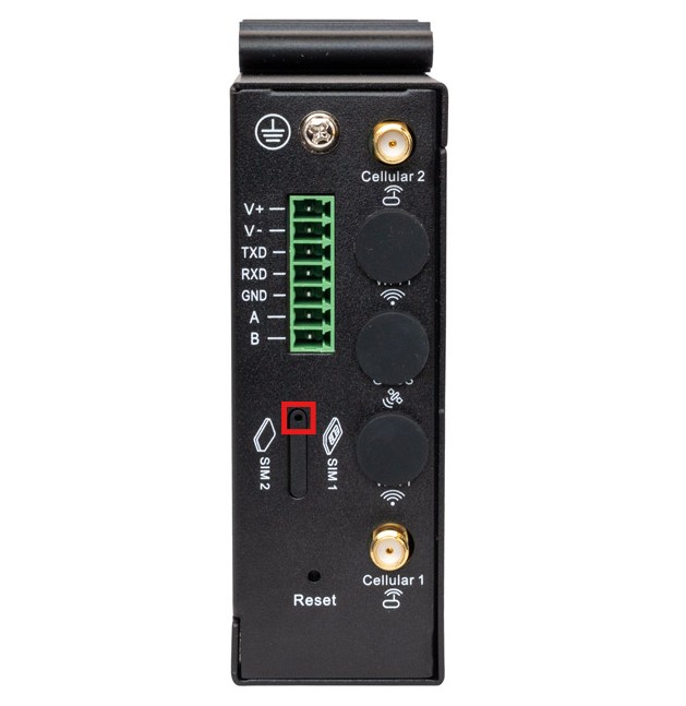
The TK500v3 is equipped to support dual nano SIM cards. To install your SIM card, use an appropriate tool to gently release the slim sled, then carefully place the SIM card into the slot.
Removing the SIM Tray
Ensure the router is powered off.
Locate the SIM tray on the side of the router.
Insert a SIM eject tool (or a straightened paperclip) into the small eject hole highlighted below.
Gently press until the tray pops out.
Carefully pull the tray completely out of the router.
Installing the SIM Card
Single-SIM Operation
If only one SIM card is being used:
Insert the SIM card into the right slot (SIM 1).
Ensure the SIM card is seated correctly in the tray.
Reinsert the tray into the router until it is fully seated.
!!!* Important: For single-SIM operation, always use SIM 1 (right side of the tray).
Dual-SIM Operation
If two SIM cards are being used:
Insert the primary SIM card into SIM 1 (right side).
Insert the secondary SIM card into SIM 2 (left side).
Verify that both SIM cards are properly seated.
Reinsert the tray into the router.
!!!* Caution: Never force the tray into the slot. If resistance is felt, remove the tray and verify the orientation of both the tray and SIM card(s).
Powering On
After the tray has been reinserted, power on the router.
Allow the router to complete the boot process.
Verify that the SIM card(s) are detected by checking the router status page
Antenna Installation
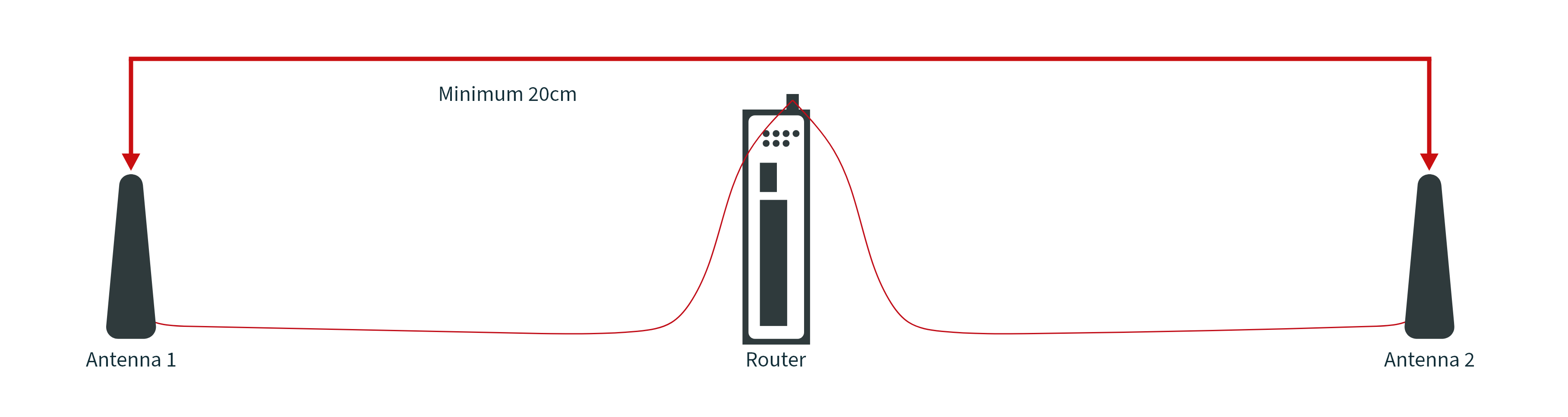
Ensure you select the appropriate connector and antenna for the desired interface. Secure the antenna connection by rotating the metal union nut clockwise.
⚠️ For optimal performance, place the antennas at least 20 cm apart.
Mounting the Device
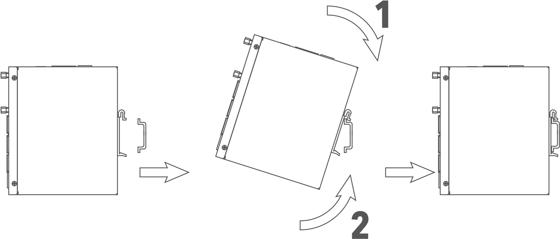
DIN rail:
Select a position with sufficient space on the DIN rail. Then place the upper part of the DIN rail mount on the DIN rail. Subsequently, press the lower side of the DIN rail mount down until the device is locked in place. This picture serves as an illustration:
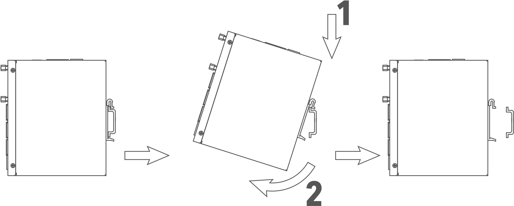
For demounting press the device from top to bottom and then pull the lower side of the device from the DIN rail (see figure).
Internet Access
The TK500v3 supports three modes of Internet access: wired, cellular, and Wi-Fi.
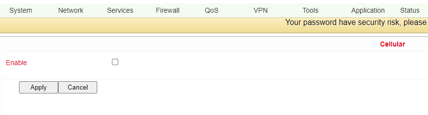
By default, the TK500v3 is set to use the Cellular interface for Internet connectivity. Should you opt to use a different connection method, please deactivate the cellular connection under “Network > Cellular” in the settings. Failure to do so may cause the device’s watchdogs to initiate regular restarts after unsuccessful attempts to enable this connection.
Connecting to the Internet via Wired Connection
Step 1: Establishing the Connection
Connect the WAN port of your router to the public network.
Link one of the LAN ports to your computer.
Power on the router to initiate the network setup.
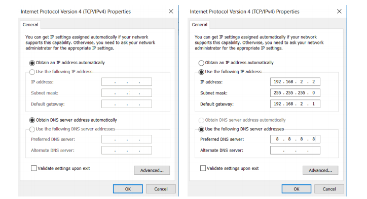
Step 2: Configuring Network Settings on Your Computer
To ensure your computer can communicate effectively with the router, configure its network settings to match the router’s IP scheme:
Automatic IP Configuration (Recommended): Set your PC to automatically obtain an IP address via DHCP. This is the simplest method as it allows the router to assign an IP address dynamically.
Manual IP Configuration: Alternatively, you can manually set an IP address for your PC. Choose an address from the range 192.168.2.2 to 192.168.2.254. Ensure the subnet mask is set to 255.255.255.0. While DNS Server and Gateway settings are optional, configuring them can enhance your network stability and performance, especially if the router serves as your primary online gateway.
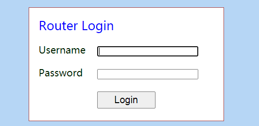
Step 3: Accessing the Router’s Configuration Interface
Open a web browser and enter the default IP address:
192.168.2.1.Enter the username and password. If your browser warns that the connection is not private, this is likely due to the self-signed certificate on the device. Click on ‘Advanced’ to verify the IP address and proceed with the access.
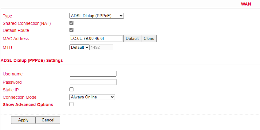
Step 4: Configuring the WAN Port
Navigate to Network > WAN in the router’s menu to configure the WAN port. You have three options for obtaining an IP address:
Dynamic DHCP: Automatically obtain an IP address from a DHCP server.
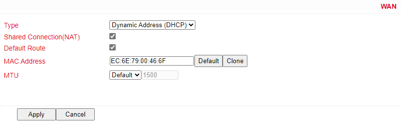
Static IP: Manually configure a static IP address.
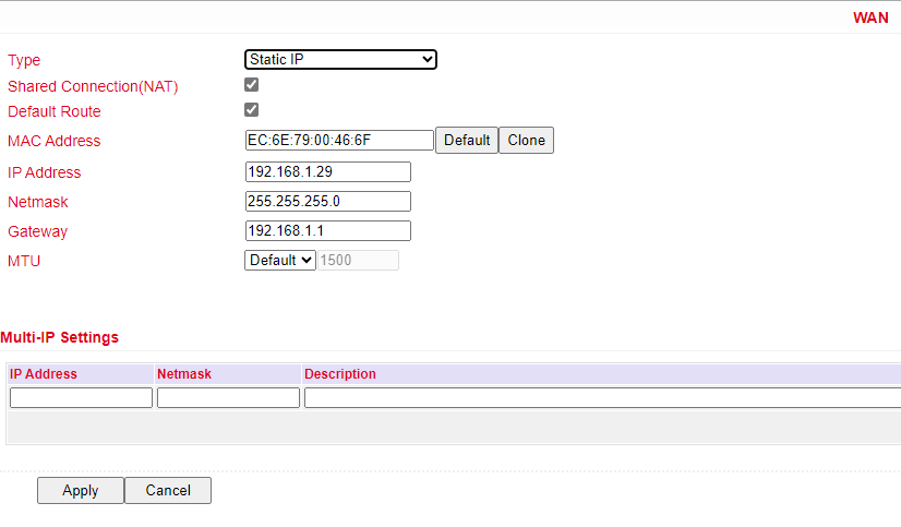
ADSL Dialup: Use ADSL for internet access. Please note that ADSL Dialup is a legacy feature and may not be tested.
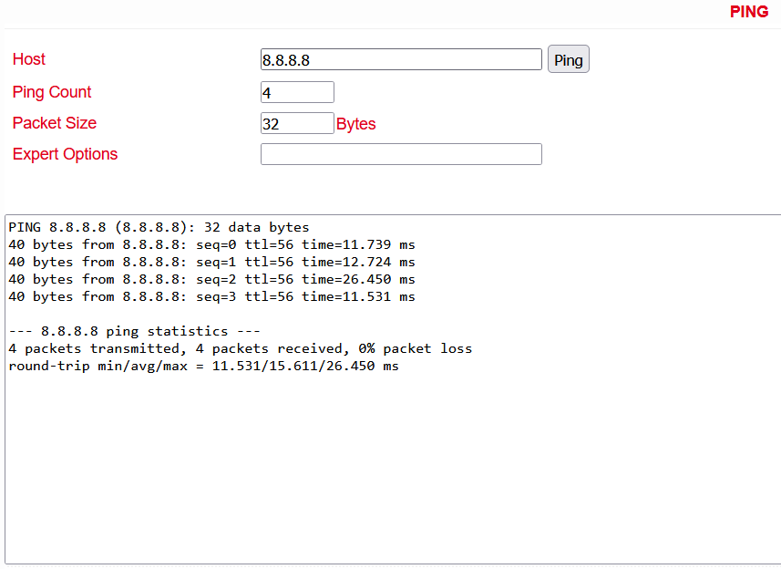
Step 5: Verify Connectivity
Check the connectivity of your network using the Ping Tool found under Tools > Ping. This will help ensure that your router is correctly configured and actively connected to the Internet.
SIM Card Internet Connection
Step 1: Installation
Insert a SIM card and attach the antennas to the router.
Note: To prevent any data loss or damage to the router or SIM card, ensure the power cable is unplugged when inserting or removing SIM cards.
Step 2: Access Router Interface
Open a browser and navigate to the router’s web management interface.
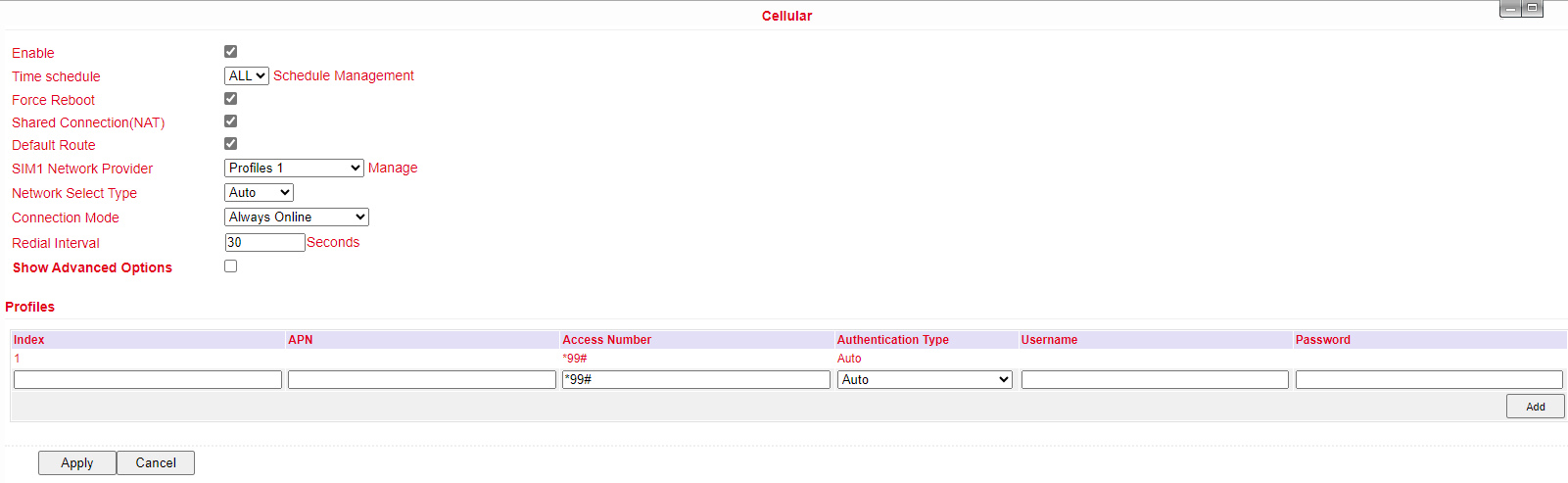
Step 3: Configure Network
Navigate to “Network > Cellular” and set up a profile. The device defaults to cellular connectivity and should connect to the internet shortly. If connection issues arise, try disabling and restarting the dial-up process. For private network SIM cards, additional configuration of the APN parameter may be required.
Step 4: Verify Connection
Check the dial-up status in the ‘Status’ section. A successful connection is indicated by ‘Connected’, along with an IP address and other relevant parameters.
Wi-Fi Internet Setup
Step 1: Connection Setup
Attach the Wi-Fi antenna and connect your computer. Access the router’s web management interface.
Step 2: Configure Wi-Fi
Choose the Wi-Fi mode:
AP Mode (Default): The router serves as an access point, distributing Wi-Fi to other devices. Ensure the router has internet access via a wired or cellular connection before enabling AP mode. Set an SSID and choose an encryption method.
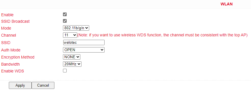
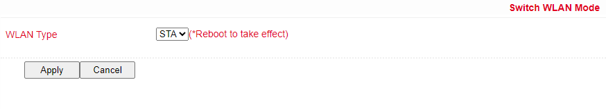
STA Mode: The router connects to an existing Wi-Fi network to access the internet.
Switch to STA mode under “Network > Switch WLAN Mode” and reboot the router.
Use “Scan” to find and connect to available networks under “Network > WLAN Client”.
Save the configured Wi-Fi settings and check the connection status under “Status”.
Factory Settings Restoration
Web Interface
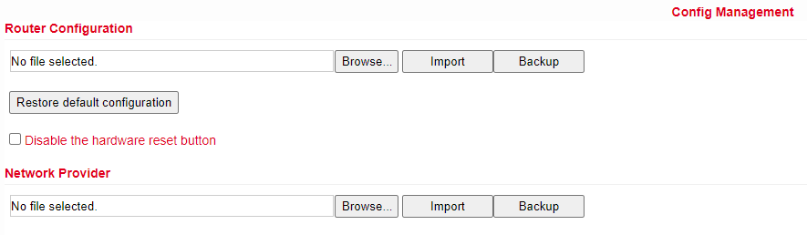
Log into the web management interface, go to “System > Config Management”, and click “Restore default configuration.” Wait for the router to reboot, indicating that it has returned to factory settings.
Hardware Method
To reset via hardware:
Press and hold the RESET button while powering on the router.
Wait until the STAT LED starts flashing, then stays steady.
Release the RESET button, press it again for 2 seconds when the LED starts flashing again.
The router will reboot with factory default settings.
Configuration Management
Go to “System > Config Management”.
To import a configuration, click “Browse” under “Router Configuration”, select a file, and click “Import”.
To export the current settings, click “Backup running-config”.
Log and Diagnostic Records
Navigate to “Status > Log” in the router’s interface to access the system log. To save the logs, click the “Download Log File” button. Additionally, you can download diagnostic data by selecting “Download System Diagnosing Data.” This information is crucial for providing detailed context when seeking support from Welotec.
SMART EMS Integration
To integrate the router with your SMART EMS management system, go to “Application > SMART EMS” in the router’s settings. Here, you can configure the router to effectively communicate and operate within your SMART EMS environment, ensuring optimal management and monitoring capabilities.
Smart-EMS Configuration
Parameter |
Description |
Default Value |
|---|---|---|
Smart-EMS |
Centralized device management for OTA updates and configuration. |
|
Server URL |
URL and port for the SMART EMS server. |
N/A |
Username |
Username for secure login via Digest Authentication. |
N/A |
Password |
Password for secure login via Digest Authentication. |
N/A |
Contact Interval |
Frequency of contact with SMART EMS in hours. |
N/A |
Send Running Config |
Option to send the current configuration to SMART EMS. |
Disabled |
Write Startup |
Save configurations received from SMART EMS as startup settings. |
Disabled |
LED-Indicator Guide for TK500v3
LED Indicator |
Status Description |
|---|---|
PWR (Power) |
Off: No power / Steady Red: Power is ON |
STAT (Status) |
Off: System error / Flashing Green: System upgrading / Steady Green: System operational |
WIFI |
Off: Wi-Fi is disabled / Flashing Green: Wi-Fi is connecting / Steady Green: Wi-Fi is active |
WAN |
Off: Network is disconnected / Flashing Green: Attempting to connect / Steady Green: Connected to the network |
Signal |
Three Green Lights: Excellent signal strength (≥20) / Two Green Lights: Good signal (10-19) / One Green Light: Poor signal (≤9) |